
High efficiency heat exchanger for freon low temperature unit

A technology of heat exchangers and freon, applied in refrigerators, refrigeration components, evaporators/condensers, etc., can solve problems such as uneven distribution of refrigerant, loss of evaporation and heat exchange, and impact on the overall efficiency of heat exchange tube bundles. Achieve the effects of improving operating efficiency and compressor reliability, increasing evaporation and boiling heat transfer coefficient, and avoiding wet compression

Active Publication Date: 2016-04-13
昆山台佳机电有限公司
View PDF4 Cites 0 Cited by
  • Summary
  • Abstract
  • Description
  • Claims
  • Application Information

AI Technical Summary

Problems solved by technology

[0004] Moreover, the refrigerant after throttling by the expansion valve is in a gas-liquid two-phase mixed state, and after entering the evaporator, the disadvantage of uneven distribution of the refrigerant in the first process is likely to occur, so that there is no liquid or little liquid in some tubes, so that These tubes lost the role of evaporation and heat exchange, which affected the overall efficiency of the heat exchange tube bundle.

Method used


Image

  • High efficiency heat exchanger for freon low temperature unit
  • High efficiency heat exchanger for freon low temperature unit

Examples


Embodiment Construction

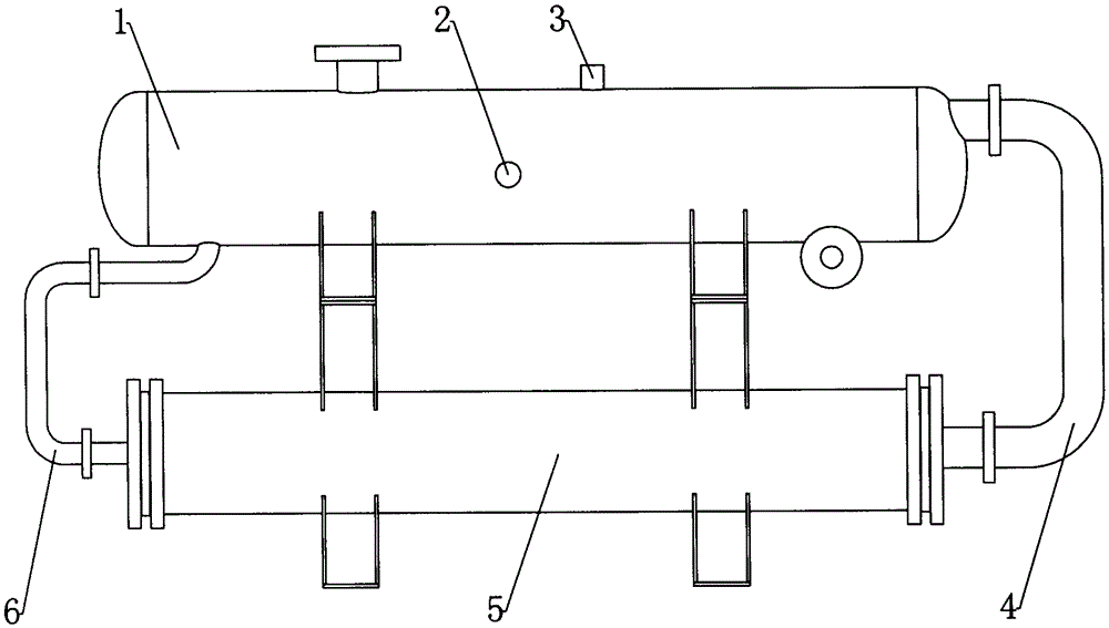
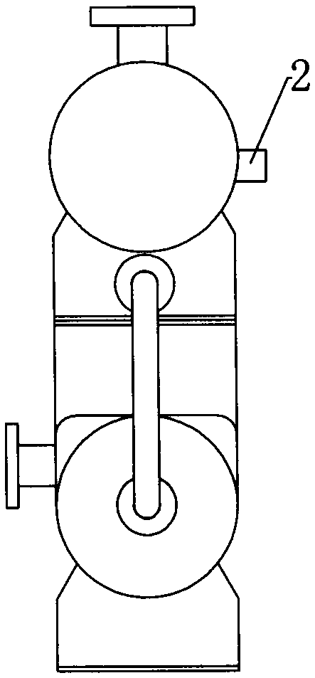
[0016] Examples, see figure 1 and figure 2 Shown: a high-efficiency heat exchanger for a Freon low-temperature unit, which includes a compressor. The high-efficiency heat exchanger for Freon cryogenic units includes a gas-liquid separation device 1 , an evaporator 5 , a gas pipe 4 and a liquid pipe 6 . Specifically, the gas-liquid separation device 1 is located above the evaporator 5 . At the same time, on one side of the gas-liquid separation device 1, the upper end of the liquid pipe 6 communicates with the gas-liquid separation device 1, and the lower end communicates with the inlet of the evaporator 5; on the other side of the gas-liquid separation device 1, the The upper end of the gas pipe 4 communicates with the gas-liquid separation device 1 , and the lower end communicates with the outlet of the evaporator 5 . In this way, the refrigerant flowing in from the condenser enters the gas-liquid separation device 1, and a certain hydrostatic column pressure is maintaine...


PUM


Abstract

The invention discloses a high-efficiency heat exchanger for a freon low-temperature unit. The freon low-temperature unit comprises a compressor. The high-efficiency heat exchanger for the freon low-temperature unit comprises a gas-liquid separation device, an evaporator, a gas pipe and a liquid pipe, wherein the gas-liquid separation device is arranged above the evaporator, and on one side of the gas-liquid separation device, the upper end of the liquid pipe is communicated with the gas-liquid separation device and the lower end of the liquid pipe is communicated with an inlet of the evaporator; on the other side of the gas-liquid separation device, the upper end of the gas pipe is communicated with the gas-liquid separation device and the lower end of the gas pipe is communicated with an outlet of the evaporator. After optimization, potential difference determined by the height difference between the gas-liquid separation device and the evaporator is bigger than the flowing resistance of a refrigerant evaporation loop; the gas-liquid separation device comprises a liquid level meter and an oil return device; one end of the oil return device stretches to a position below the liquid level of the gas-liquid separation device and the other end of the oil return device is connected with the compressor. The high-efficiency heat exchanger for the freon low-temperature unit has the advantages that the consumption is lower, the heat exchange efficiency is high and the refrigerating capacity can be improved.

Description

technical field [0001] The invention relates to the technical field of refrigeration devices, in particular to a high-efficiency heat exchanger for Freon low-temperature units. Background technique [0002] The research on energy saving of refrigeration equipment mainly focuses on four important equipment in the system: compressor, two devices (evaporator, condenser) and throttling mechanism. Among them, the performance improvement of the evaporator in the two devices is particularly important. [0003] At present, when the refrigeration unit is operating at low temperature, since the solubility of the refrigerant and the refrigerating oil changes with the temperature, even if an oil separator is installed on the compressor exhaust pipe, the refrigerating oil will still be in the process of operation. It is entrained into the evaporator, and the viscosity of the refrigerated oil entering the evaporator increases, and it is not easy to be brought back to the compressor by th...

Claims


Application Information

Patent Timeline
Patent Type & Authority Patents(China)
IPC IPC(8): F25B39/02F25B43/02
Inventor 谢禅芮火根
Owner 昆山台佳机电有限公司
Learn More