
A micro-rail vehicle and its suspension device

A suspension device and vehicle technology, which is applied in the field of micro-rail transportation, and can solve the problems that the suspension vibration reduction mechanism cannot be used, the vibration of the running part cannot be effectively blocked from being transmitted to the carriage, and the vibration reduction effect is poor.

Active Publication Date: 2021-03-30
CRRC TANGSHAN CO LTD
View PDF5 Cites 0 Cited by
  • Summary
  • Abstract
  • Description
  • Claims
  • Application Information

AI Technical Summary

Problems solved by technology

Due to the small space size of the micro-rail vehicle, it is not possible to use the complex suspension damping mechanism of the suspended monorail vehicle
[0003] The structure of the suspension device of the existing micro-rail vehicle is simple, the boom and the carriage are directly connected by bolts, and the relative swing between the carriage and the running part is realized by the pin shaft, so the existing micro-rail vehicle cannot effectively block the vibration generated by the running part The problem of transmission to the carriage makes the existing micro-rail vehicles have poor vibration damping effect and cannot effectively limit the free swing of the vehicle

Method used


Image

  • A micro-rail vehicle and its suspension device
  • A micro-rail vehicle and its suspension device
  • A micro-rail vehicle and its suspension device

Examples


Embodiment 1

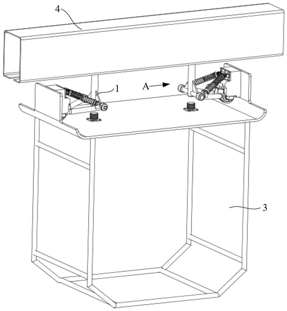
[0044] 本实施例提供了一种用于微轨车辆的悬挂装置1,微轨车辆的运行结构示意图可以参考 figure 1 , figure 2 with Figure 4 ,悬挂装置1吊装于轨道4内的走行部2上,车厢3通过悬挂装置1悬挂于走行部2上,并与走行部2形成一体结构;每个车厢3配置有前后间隔设置的两个走行部2,走行部2沿轨道4运动,每个走行部2的底端安装有一个悬挂装置1,并通过两个走行部2和与走行部2相配套的悬挂装置1将车厢3吊装于轨道4上,使车厢3能够在走行部2的带动下沿轨道4移动,实现运输乘客的目的;

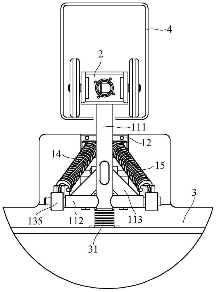
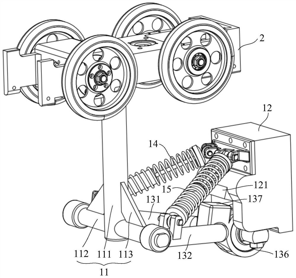
[0045] Please refer to image 3 with Figure 5 ,该悬挂装置1包括悬架11、安装座12、V形杆13、第一弹性件14以及第二弹性件15;悬架11的顶部吊装于走行部2,悬架11的底部安装有V形杆13;安装座12固定安装于车厢3的顶部,并与悬架11平行设置;如 figure 1 , Figure 4 with Figure 8 结构所示,沿轨道4的延伸方向,在车厢3的顶部两端固定安装有相对设置的两个安装座12;在悬架11和安装座12的底部安装有V形杆13,V形杆13的两端分别与悬架11和安装座12之间转动连接,V形杆13能够相对悬架11和安装座12转动;

[0046] Such as Figure 9 with Figure 10As shown in the structure, the V-shaped rod 13 includes a first strut 131 and a second strut 132, and the connecting ends 133 of the first strut 131 and the second strut 132 are rotatably connected to the bottom of the mounting base 12, and the first strut 131 The separation ends 134 of the second pole 132 are respectively rotatably connected to both sides of the bottom of the...

Embodiment 2

[0052] This embodiment also provides a micro-track vehicle, such as figure 1 with Figure 4 As shown in the structure, the micro-rail vehicle includes a running part 2 and a carriage 3, and also includes any suspension device 1 provided in the above-mentioned embodiments. The suspension device 1 hangs the carriage 3 on the bottom of the running part 2. The running part 2 can be The track 4 moves; two suspension devices 1 oppositely arranged are connected between the running part 2 and the carriage 3, and the two suspension devices 1 are arranged along the traveling direction of the running part 2, and the two suspension devices 1 are installed on the top of the carriage 3 , and symmetrically arranged, so that the compartment 3 is suspended on the running part 2 from both ends of the traveling direction of the micro-rail vehicle;

[0053] Such as Figure 5 , Image 6 with Figure 7 As shown in the structure, an elastic stopper 31 corresponding to the bottom end surface of t...


PUM


Abstract

The invention relates to the technical field of micro-rail traffic, in particular to a micro-rail vehicle and a suspension device thereof. The suspension device comprises a suspension, a mounting base, a V-shaped rod, a first elastic piece and a second elastic piece; the top of the suspension is hoisted on a walking part; the mounting base is fixedly mounted at the top of the carriage; the V-shaped rod comprises a first supporting rod and a second supporting rod, the connecting ends of the first supporting rod and the second supporting rod are rotationally connected to the bottom of the mounting base, and the separating ends of the first supporting rod and the second supporting rod are rotationally connected to two sides of the bottom of the suspension; the first elastic piece and the second elastic piece are distributed in a splayed shape, the top end of the first elastic piece and the top end of the second elastic piece are hinged to the top of the mounting base, the bottom end of the first elastic piece is hinged to the first supporting rod, and the bottom end of the second elastic piece is hinged to the second supporting rod. According to the suspension device, the vibration reduction performance of the micro-rail vehicle can be enhanced, free swing of the carriage can be limited, and the riding comfort of passengers is improved.

Description

technical field [0001] 本申请涉及微轨交通技术领域,具体地,涉及一种微轨车辆及其悬挂装置。 Background technique [0002] 现有微型悬挂车辆的悬挂装置需要将走行部的纵向力(牵引力和制动力)传递到吊挂的车厢,同时还要承担车厢重力等垂向力,而且还要保证微型悬挂车辆能够很好地通过水平曲线和坡道(竖曲线)。由于微轨车辆的空间尺寸较小,无法采用悬挂式单轨车辆的复杂的悬挂减振机构。 [0003] 现有微轨车辆的悬挂装置结构简单,吊杆与车厢之间直接通过螺栓连接,车厢和走行部之间的相对摆动靠销轴实现,导致现有微轨车辆不能有效阻隔走行部产生的振动向车厢传递的问题,使得现有微轨车辆减振效果差且不能有效限制车辆的自由摆动。 Contents of the invention [0004] 本申请实施例中提供了一种微轨车辆及其悬挂装置,该悬挂装置能够增强微轨车辆的减振性能且能够限制车厢的自由摆动,提升乘客的乘坐舒适性。 [0005] 根据本申请实施例的第一个方面,提供了一种用于微轨车辆的悬挂装置,该悬挂装置包括悬架、安装座、V形杆、第一弹性件以及第二弹性件; [0006] 所述悬架的顶部吊装于走行部; [0007] 所述安装座固定安装于车厢的顶部,并与所述悬架平行设置; [0008] 所述V形杆包括第一支杆和第二支杆,所述第一支杆和所述第二支杆的连接端转动连接于所述安装座的底部,所述第一支杆和所述第二支杆的分离端分别转动连接于所述悬架底部的两侧; [0009] 所述第一弹性件与所述第二弹性件呈“八”字形分布,所述第一弹性件的顶端和所述第二弹性件的顶端均铰接于所述安装座的顶部,所述第一弹性件的底端铰接于所述第一支杆朝向所述悬架的一端,所述第二弹性件的底端铰接于所述第二支杆朝向所述悬架的一端。 [0010] 优选地,所述悬架包括垂直连接的吊杆和横杆; [0011] 所述吊杆沿竖直方向设置; [0012] 所述横杆固定连接于所述吊杆的底端,并以所述吊杆的轴心线为对称轴对称设置在所述吊杆的两侧。 [0013] 优选地,在所述横杆与所述吊杆之间设置有加强肋。 [0014] 优选地,在所述第一支杆和所述第二支杆的分离端均固定安装有一个套筒; [0015]...

Claims


Application Information

Patent Timeline
Patent Type & Authority Patents(China)
IPC IPC(8): B61B12/04
CPCB61B12/04
Inventor 耿庆厚李霞曹增招王艮川刘茜
Owner CRRC TANGSHAN CO LTD
Learn More