Dust suction guide structure, dust suction mechanism and sweeping robot
A technology of guiding structure and dust-absorbing mechanism, which is applied in the field of sweeping robots, can solve problems such as clogging and dust-absorbing, winding, etc., and achieve the effect of improving efficiency, effective dust-absorbing efficiency, and ideal sweeping and cleaning effects
- Summary
- Abstract
- Description
- Claims
- Application Information
AI Technical Summary
Problems solved by technology
Method used
Image
Examples
Embodiment 1
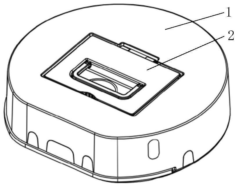
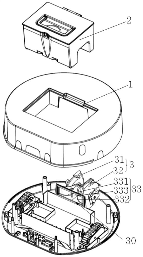
[0130] reference Figures 2a ~ 2d The embodiment of the present invention provides a sweeping robot. The sweeping robot has a vacuuming mechanism including a vacuuming guide structure 10 provided on the bottom of the outer casing 1 and a dust cartridge 2 and a fan 3 provided inside the outer casing 1, wherein the dust box 2 is The inlet 20 is in communication with the airway suction port 12 on the bottom of the outer casing 1, and the outlet of the collecting cartridge 2 (not shown) communicates with the inlet 30 of the fan 3.
[0131] The fan 3 includes a first fan 31 and a second fan 32, and the first fan 31 and the second fan 32 communicate with the dust box 2 through the suction guide member 33. The suction guide member 33 includes an independent first suction passage 331 and a second suction passage 332 that communicates with the first suction passage 331, the second fan 32 and the The second suction passage 332 is in communication. Wherein the suction guide member 33 is provi...
Embodiment 2
[0138] reference Figures 3A ~ 3D A vacuum-cement guide structure provided in the embodiment of the present invention is provided at the outer casing bottom 11 of the diaaching mechanism, which includes a flap 12 and a trench 13, and a trench 13, which is provided on the bottom portion 11 of the outer casing. The trench 13 is provided between the front end of the surface of the outer casing bottom 11 and the airway suction port 12 in communication with the airway suction port 12 to constitute dust guiding dust into the air inner mouth 12. Guided airway.
[0139] Specifically, the front end 131 of the trench 13 is smoothly connected to the front end edge of the outer casing bottom 11, and the rear end 132 of the groove 13 is connected to the front side 121 of the airway suction port 12, the depth of the trench 13 The front end 131 gradually increases to its rear end 132, and the width D1 of the rear end 132 of the trench 13 is less than or equal to the length of the front side 121 of ...
Embodiment 3
[0146] reference Figures 5a ~ 5c A vacuum-ceased guide structure provided in the embodiment of the present invention is provided at the outer casing bottom 11 of the vacuuming mechanism, which includes a wind hole suction 12 disposed on the bottom portion 11 and a wind. The first trenches 133 and the second trench 134 on both sides of the trading port 12, the first trench 133, and the second trench 133 communicate with the airway suction port 12, respectively, and the dust is guided to the wind. Dust Guide Dust Guide in the Touch Exit 12.
[0147] Specifically, one end 1331 of the first trench 133 is connected to the airway suction port 12, and the other end 1332 of the first trench 133 is smooth transition to the edge of the outer casing bottom 11. One end 1341 of the second trench 134 is connected to the airway suction port 12, and the other end 1342 of the second trench 134 is smoothly connected to the edge of the outer casing bottom 11. The wind turbine suction port 12 is a re...
PUM
 Abstract
Description
Claims
Application Information
 - R&D
- Intellectual Property
- Life Sciences
- Materials
- Tech Scout
- Unparalleled Data Quality
- Higher Quality Content
- 60% Fewer Hallucinations
Browse by: Latest US Patents, China's latest patents, Technical Efficacy Thesaurus, Application Domain, Technology Topic, Popular Technical Reports.
© 2025 PatSnap. All rights reserved.Legal|Privacy policy|Modern Slavery Act Transparency Statement|Sitemap|About US| Contact US: help@patsnap.com


