Core shaft lifting mechanism

A hoisting and mandrel technology, applied in the direction of transportation and packaging, load hanging components, etc., can solve the problem of low safety performance of the mandrel replacement operation

Active Publication Date: 2020-09-29
CHINA FIRST METALLURGICAL GROUP
View PDF10 Cites 0 Cited by
  • Summary
  • Abstract
  • Description
  • Claims
  • Application Information

AI Technical Summary

Problems solved by technology

[0003] One of the purposes of this application is to provide a mandrel hoisting mechanism, aiming to improve the existing problem of low safety performance of the mandrel replacement operation

Method used


Image

  • Core shaft lifting mechanism
  • Core shaft lifting mechanism

Examples


Embodiment

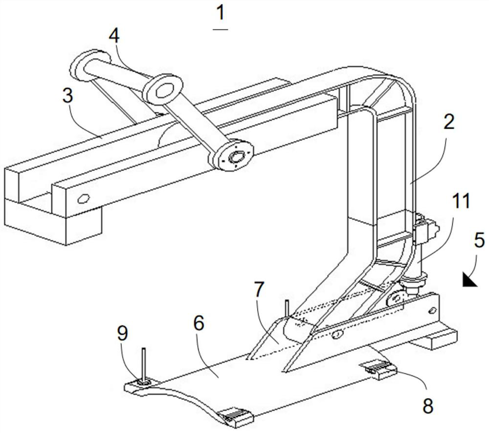
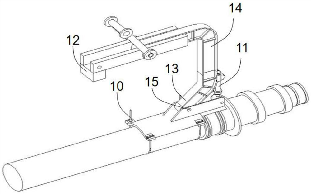
[0034] Please refer to figure 1 , with reference to figure 2 , the application provides a mandrel hoisting mechanism 1, including a support frame 2, a connecting frame 3, a hoisting assembly 5 and a hydraulic cylinder 11, and the hoisting assembly 5 includes an arc limit plate 6 and two positioning plates 7; wherein, the connecting frame One end of 3 is vertically connected to the top of the support frame 2; the bottom of the lifting lug 4 is hinged on the middle position of the connecting frame 3, and the device is hung on the crane hook through the lifting lug 4 during hoisting; A counterweight 12 is fixedly installed on the bottom of the free end of the s The upper surfaces of the plates 6 are perpendicular to each other, and the arrangement direction of the two is parallel to the length direction of the arc-shaped limiting plate 6 . The arc-shaped limit plate 6 is made of a thicker arc-shaped steel plate, and its arc surface faces downward, which can wrap the mandrel to...


PUM


Abstract

The invention provides a core shaft lifting mechanism, and belongs to the field of mechanical equipment. The core shaft lifting mechanism comprises a supporting frame, a connecting frame, a lifting lug, a lifting assembly and a hydraulic cylinder; one end of the connecting frame is connected to the top of the supporting frame at an angle; the lifting lug is mounted on the connecting frame; the lifting assembly comprises an arc-shaped limiting plate and two positioning plates, and the two positioning plates are parallelly mounted on the upper surface of the arc-shaped limiting plate in a spacedmode; the arc-shaped limiting plate is bent in the direction away from the positioning plates, two connecting grooves are formed in one side of the arc-shaped limiting plate in a spaced mode, and twobolt holes are formed in the other side of the arc-shaped limiting plate in a spaced mode; the bottom of the supporting frame is mounted between the two positioning plates; and the hydraulic cylinderis mounted on the supporting frame, and the driving end is in transmission connection with the upper surface of the arc-shaped limiting plate. The core shaft lifting mechanism is easy to operate, high in stability, rapid and convenient to use and high in safety performance.

Description

technical field [0001] The present application relates to the field of mechanical equipment, in particular to a mandrel hoisting mechanism. Background technique [0002] The coiling mandrel in the hot rolling mill is an important production equipment. After a cycle of use (usually about 50 days), it must be replaced. Due to the irregular shape of the mandrel and the limited hoisting space, the replacement of the mandrel is limited Great trouble came. The original use of steel wire rope hoisting, not only the mandrel is easy to damage, the mandrel is inclined during hoisting, there will be sliding, collision with the surrounding equipment, causing damage to the mandrel and other equipment, and may slip off and separate from the wire rope, which is prone to safety accidents. . SUMMARY OF THE INVENTION [0003] One of the objectives of the present application is to provide a mandrel hoisting mechanism, which aims to improve the problem of low safety performance of the exist...

Claims


Application Information

Patent Timeline
IPC IPC(8): B66C1/12B66C13/08
CPCB66C1/12B66C1/122B66C13/08
Inventor 岳峰熊虎
Owner CHINA FIRST METALLURGICAL GROUP
Why Eureka
Try Eureka