Mask alignment mark combination, mask alignment system, photoetching device and photoetching method

An alignment mark and mask alignment technology, applied in the field of lithography, can solve problems such as the need to improve the accuracy and the measurement error of the mask alignment position, and achieve the effect of improving the measurement accuracy of the mask alignment

Active Publication Date: 2020-10-09
SHANGHAI MICRO ELECTRONICS EQUIP (GRP) CO LTD
View PDF5 Cites 0 Cited by
  • Summary
  • Abstract
  • Description
  • Claims
  • Application Information

AI Technical Summary

Problems solved by technology

However, in the existing mask alignment process, there is a certain error in the measurement of the mask alignment position, and the accuracy needs to be improved.

Method used


Image

  • Mask alignment mark combination, mask alignment system, photoetching device and photoetching method
  • Mask alignment mark combination, mask alignment system, photoetching device and photoetching method
  • Mask alignment mark combination, mask alignment system, photoetching device and photoetching method

Examples


Embodiment 1

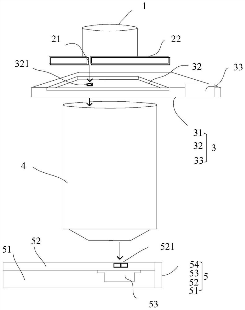
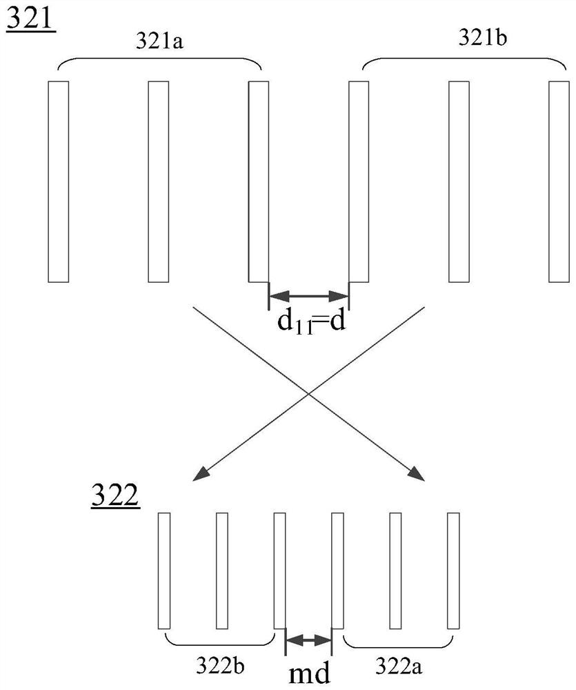
[0045] In this embodiment, the first alignment mark branch 321 and the second alignment mark branch 521 both include two sets of gratings for illustration. Such as figure 2 As shown, the first alignment mark branch 321 includes two groups of gratings 321a, 321b, and the interval between the two groups of gratings 321a, 321b is the first width dimension d 11 , let d 11 =d, wherein, d is a constant, and the projection assembly 4 projects the transmission image of the first alignment mark branch 321 onto the surface of the workpiece stage reference plate 52 to form two non-overlapping aerial images 322a , 322b, wherein, aerial image 322a is the aerial image that grating 321a produces, aerial image 322b is the aerial image that grating 321b produces, because the projection magnification of projection assembly 4 is m, aerial image 322a, 322b are two groups of gratings 321a, 321b The ratio is reduced, so the width dimension of the interval between the spatial images 322a and 322b...

Embodiment 2

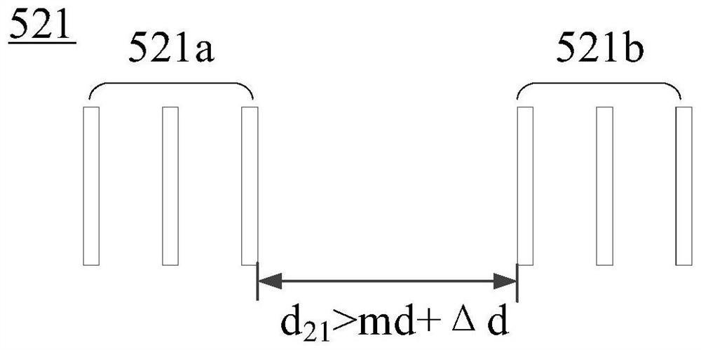
[0059] Such as Figure 6-Figure 8 As shown, the difference from Embodiment 1 is that in this embodiment, both the first alignment mark branch 321 and the second alignment mark branch 521 include more than two groups of gratings, for example, N groups (N greater than or equal to 3). Such as Figure 6 As shown, the first width dimension of the interval between each group of gratings in the first alignment mark branch 321 is d 11 =d, after being projected by the projection component, N aerial images 322 are formed, and the space between each aerial image is md. Figure 7 , the second alignment mark branch 521 also includes N groups of gratings, and the interval between each group of gratings is the second width dimension d 21 , the third width dimension d 22 ...the n+1th width dimension d 2n , and satisfy the following relation: d 21 >md+1*Δd, d 22 >md+2*Δd...n+1th width dimension d 2n >md+n*Δd, since the size of each aerial image in this embodiment is all equal, so Δd is...


PUM


Abstract

The invention provides a mask alignment mark combination, a mask alignment system, a photoetching device and a photoetching method. A first alignment mark branch and a second alignment mark branch which comprise a plurality of groups of gratings are respectively arranged on a mask plate and a reference plate of a workpiece table, so that in the alignment scanning process, a radiation detector canmeasure radiation information of a plurality of space images; furthermore, a plurality of coarse mask alignment positions are obtained by combining the mask plate detected by the first position detector and the second position detector and the position information of the reference plate of the workpiece table, and a fine mask alignment position is calculated according to the plurality of coarse mask alignment positions, so the mask alignment measurement precision is improved.

Description

technical field [0001] The invention relates to the technical field of photolithography, in particular to a mask alignment mark combination, a mask alignment system, a photolithography device and a method thereof. Background technique [0002] In the lithography apparatus, by using the combination of alignment marks in the alignment system to carry out alignment scanning to obtain alignment information such as optical information and position information of each alignment mark branch, and correspondingly process these information to obtain mask alignment The positional relationship between the mark combination and the alignment mark combination on the workpiece table reference plate, the alignment system of the lithography device includes: lighting components, irradiation windows and their control boards, mask plates and their mask alignment mark branches, masks stage, mask stage position detector, projection assembly, workpiece stage reference plate and its reference plate ...

Claims


Application Information

Patent Timeline
IPC IPC(8): G03F9/00G03F7/20
CPCG03F7/7085G03F9/7076G03F9/708G03F9/7088
Inventor 陈小娟忻斌杰李术新
Owner SHANGHAI MICRO ELECTRONICS EQUIP (GRP) CO LTD
Why Eureka
Try Eureka