Method for processing alignment mark measuring signals

A technique for measuring signals and processing methods, applied in the field of lithography devices

Active Publication Date: 2011-11-23
SHANGHAI MICRO ELECTRONICS EQUIP (GRP) CO LTD
View PDF11 Cites 4 Cited by
  • Summary
  • Abstract
  • Description
  • Claims
  • Application Information

AI Technical Summary

Problems solved by technology

The alignment signal fitting section is closely related to the pre-alignment position of the mark

Method used


Image

  • Method for processing alignment mark measuring signals
  • Method for processing alignment mark measuring signals
  • Method for processing alignment mark measuring signals

Examples


Embodiment Construction

[0028] In the following, preferred embodiments according to the present invention will be described in detail with reference to the accompanying drawings. For the convenience of describing and highlighting the present invention, relevant components existing in the prior art are omitted from the drawings, and the description of these known components will be omitted.

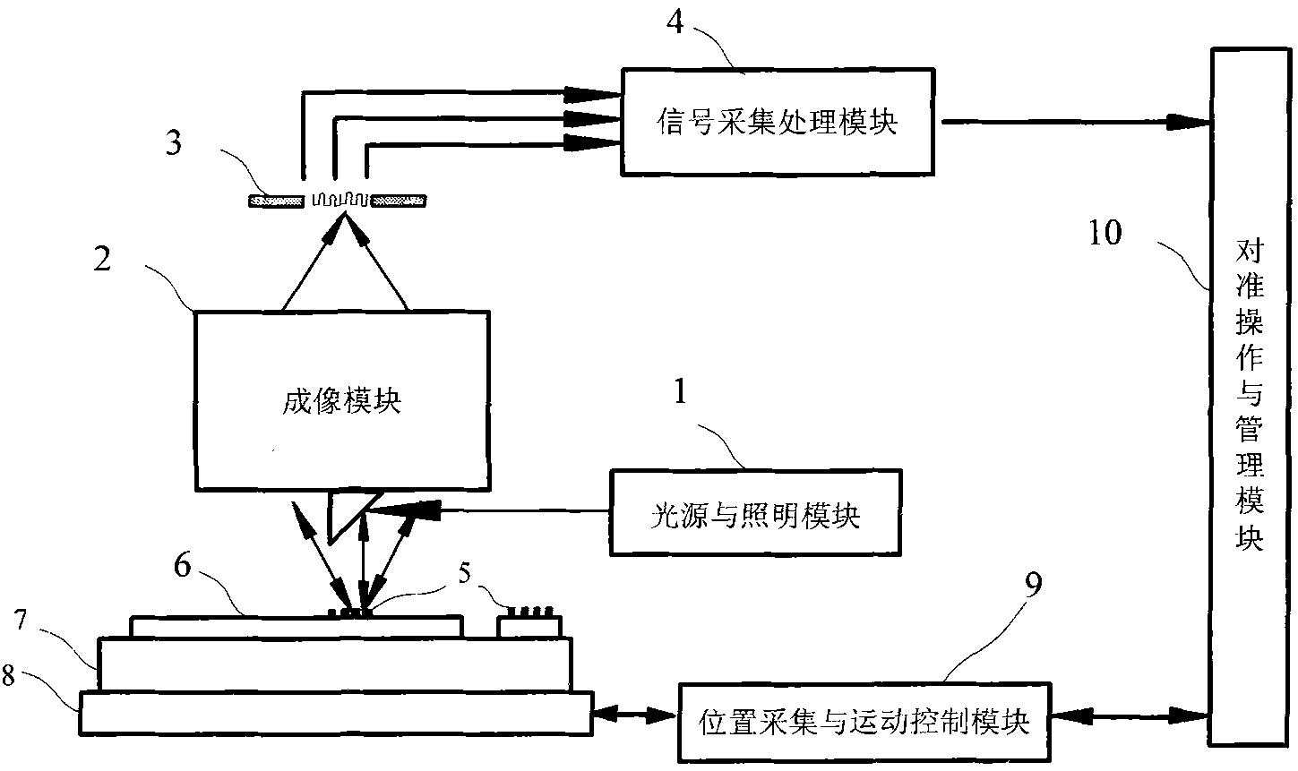
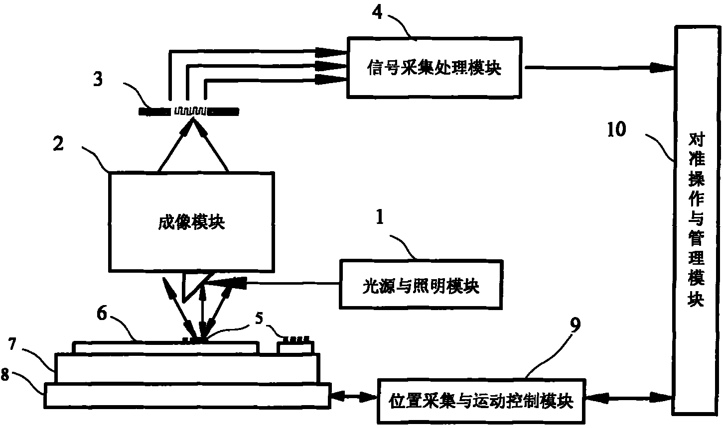
[0029] figure 2Shown is an alignment system used in the signal processing method according to the invention. The alignment system includes: a light source and illumination module 1; an imaging module 2; a reference grating 3; a signal acquisition and processing module 4; an alignment mark 5, including a reference plate mark and a silicon wafer mark on a silicon wafer 6; a workpiece table 7 ; Motion platform 8 ; position acquisition and motion control module 9 ; alignment operation and management module 10 . The light source and illumination module 1 provides an illumination beam to irradiate the alignment mark...


PUM


Abstract

The invention provides a method for processing alignment mark measuring signals. The method comprises the following steps of: after sampling an alignment signal, fitting the signal by a fitting model to solve the best alignment position; performing model fitting by using a result acquired by light intensity sampling and position sampling; fitting the period of the signal while fitting model parameters so as to determine the phase of the signal; and finally solving and determining the best alignment position.

Description

technical field [0001] The invention relates to photolithography devices in the field of integrated circuit or other micro-device manufacturing, in particular to a signal processing method for alignment mark measurement. Background technique [0002] In the manufacturing process of semiconductor IC integrated circuits, a complete chip usually needs to undergo multiple photolithography exposures before it can be completed. Except for the first photolithography, before exposure, the photolithography of other levels must accurately position the graphics of this level and the graphics left by the exposure of the previous level to ensure the correct relative position between the two layers of graphics, that is, set carve. Overlay errors are usually only allowed within 1 / 3 of the lithographic resolution. There are many factors that affect the overlay accuracy, including the positioning accuracy of the workpiece table, the measurement error of the position measurement system, the...

Claims


Application Information

Patent Timeline
IPC IPC(8): G03F9/00
Inventor 李运锋赵新韩悦韦学志
Owner SHANGHAI MICRO ELECTRONICS EQUIP (GRP) CO LTD
Why Eureka
Try Eureka