Anomaly detection in pneumatic system

An abnormality and error detection technology, applied in the direction of pneumatic program control, general control system, error detection/correction, etc., can solve the problems of error monitoring and failure to adopt

Pending Publication Date: 2020-10-09
FESTO AG & CO KG
View PDF3 Cites 0 Cited by
  • Summary
  • Abstract
  • Description
  • Claims
  • Application Information

AI Technical Summary

Problems solved by technology

[0005] However, known methods cannot be used if error monitoring is to be carried out on plants with only a minimal sensor system, such as a pneumatic system with only two final position sensors

Method used


Image

  • Anomaly detection in pneumatic system
  • Anomaly detection in pneumatic system
  • Anomaly detection in pneumatic system

Examples


Embodiment Construction

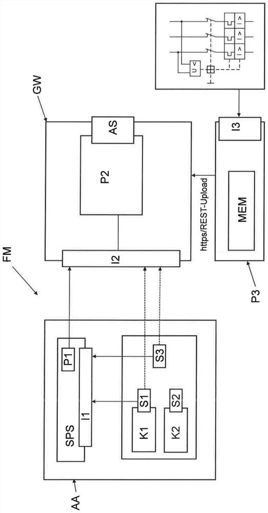
[0076] The present invention is technically used for monitoring a pneumatic system as an example of an automation system or device including various field devices (hereinafter also referred to as components) controlled by a control device such as a PLC. In particular, errors should be identified in good time, and preferably at some point in time before individual components fail or cause errors in the device. For this purpose, the error detection module will be used, and the following will be compared to the figure 1 This error detection module is explained in more detail.

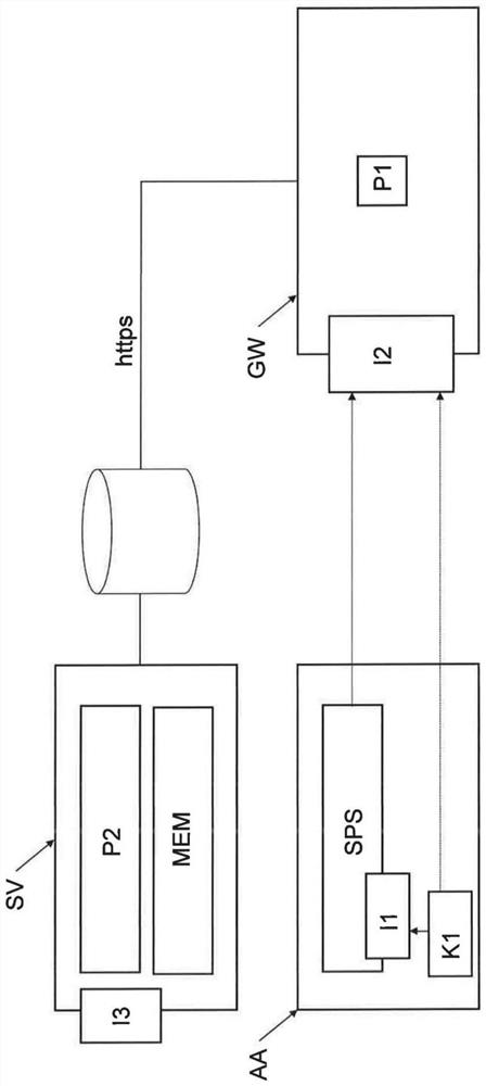
[0077] The invention has the advantage that early error detection of complex, multi-component, preferably pneumatic automation systems is possible despite the fact that only little measurement data is available and can be similarly operated with a minimum of sensor systems. In particular, error positioning can be provided despite the use of only two digital sensors and one switching command, especially fo...


PUM


Abstract

The invention relates to error detection and positioning in a pneumatic system (AA), in particular to an error detection module (FM), comprising: a read-in interface (I1) for reading in a digital signal from automation equipment (AA); a first processor unit (P1) designed to execute a detection algorithm (S2) in order to calculate an abnormality score of the automation equipment (AA) on the basis of the read-in signal group; a second processor unit (P2) designed to execute a machine positioning method (S34) for positioning an error when the abnormality score calculated by the first processor unit(P1)indicates abnormal, wherein the machine positioning method (S34) has been trained in the training phase in order to calculate, for the calculated anomaly score, a probability of possible error causes associated with the individual components (K) of the automation equipment (AA) on the basis of the detected loop diagram of the automation equipment (AA) and to provide this probability as a result.

Description

technical field [0001] The present invention relates to technical error detection and localization in pneumatic automation equipment, for example in production equipment comprising actuators and sensors, and in particular to an error detection module, an error detection system, a method and a computer program. Background technique [0002] Basic high quality, robustness and availability requirements are placed on components or field devices in different types of automation equipment. Failure or failure of in-process field devices can be extremely costly, especially if manufacturing is disrupted as a result. A high degree of technical sophistication is therefore employed in field devices in order to significantly reduce the risk of failure or to be able to detect and report defects independently. The functions are redundantly integrated into the field device, the measurement results are permanently monitored and verified internally. The requirement to protect against field ...

Claims


Application Information

Patent Timeline
Patent Type & Authority Applications(China)
IPC IPC(8): G06F11/07G06N20/00G01D18/00
CPCG06F11/0751G06N20/00G01D18/00G05B23/024G05B23/0281G05B19/44G05B19/4183G06F2218/08G06F2218/12
Inventor D·克劳斯T·施特雷彻特W·高赫尔
Owner FESTO AG & CO KG
Why Eureka
Try Eureka