Expressway signboard cleaning device

A technology for cleaning devices and highways, applied in cleaning methods and utensils, cleaning methods using liquids, cleaning methods using tools, etc. The effect of fast speed, wide range and large water outlet area

Active Publication Date: 2020-10-13
王里平
View PDF7 Cites 0 Cited by
  • Summary
  • Abstract
  • Description
  • Claims
  • Application Information

AI Technical Summary

Problems solved by technology

[0005] In order to overcome the shortcomings that it is very dangerous for workers to clean signs on the lifting frame, and the height limits the operating space of workers, it is difficult to clean, and the scope of each cleaning is limited and the efficiency is very low. The technical problem to be solved : Provide a kind of simple operation, and use safe expressway sign cleaning device

Method used


Image

  • Expressway signboard cleaning device
  • Expressway signboard cleaning device
  • Expressway signboard cleaning device

Examples


Embodiment 1

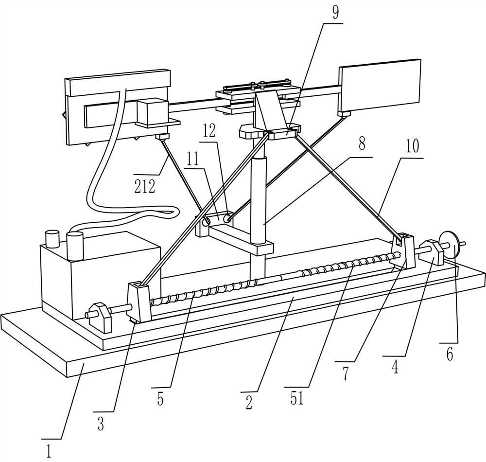
[0023] A cleaning device for expressway signs, such as Figure 1-5 As shown, it includes: mounting plate 1, chute plate 2, sliding block 3, fixed block 4, screw rod one 5, screw rod two 51, hand turntable 6, moving block 7, telescopic rod 8, lifting plate 9, Connecting rod 10, lifting mechanism and cleaning mechanism, the top of the mounting plate 1 is fixedly connected with a chute plate 2, the chute plate 2 is symmetrically slidingly connected with a sliding block 3, and the upper side of the chute plate 2 is fixedly connected with two fixed blocks 4. It is distributed symmetrically. The fixed block 4 on the left is movably provided with a screw rod 5, and the fixed block 4 on the right is movably provided with a screw rod 51, which is symmetrically distributed with the screw rod 5. The right end of the first 5 is fixedly connected with the left end of the second screw 51. The first screw 5 and the second 51 thread are matched with a moving block 7. The bottom of the moving bl...

Embodiment 2

[0026] On the basis of Example 1, such as Figure 1-5 As shown, the lifting mechanism includes a lower universal seat 11, a lower universal ball 12, a fixed seat 13, a lower guide plate 14, a movable rod 15, an upper guide plate 16, a movable rod 17, a guide rod 18, and a clamping plate 19. The cleaning plate 20, the upper universal seat 21, the upper universal ball 211 and the second connecting rod 212, the lower part of the telescopic rod 8 is fixedly connected with the lower universal seat 11, and the rear part of the lower universal seat 11 is symmetrically connected with the lower part. The universal ball 12, the lifting plate 9 is fixedly connected with a fixed seat 13, the middle and rear side of the fixed seat 13 is fixedly connected with a lower guide plate 14, and the sliding groove of the lower guide plate 14 is slidably connected with two movable rods 15 to form Distributed symmetrically, the upper rear side of the fixed seat 13 is fixedly connected with an upper gui...
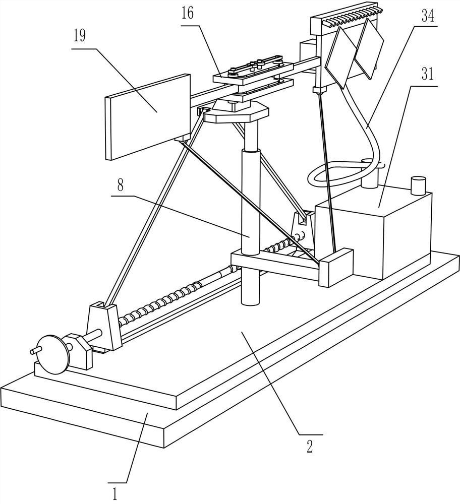
Embodiment 3

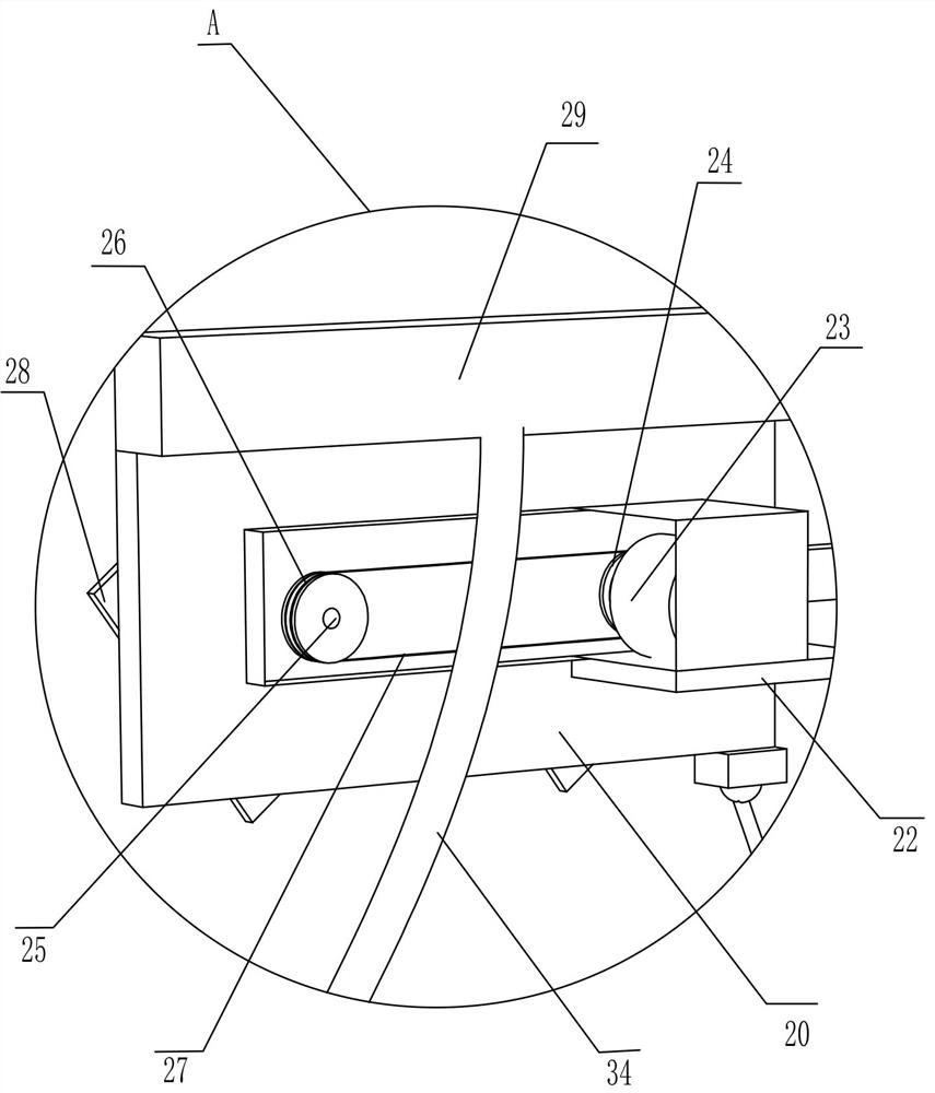
[0031] On the basis of Example 2, such as Figure 3-6 As shown, it also includes a branch box 29, a water spray pipe 30, a water tank 31, a water inlet pipe 32, a water pump 33, and a water pipe 34. The upper part of the cleaning plate 20 is fixedly connected with a branch box 29, and the rear side of the branch box 29 is fixedly connected with water spray The pipes 30 and the water spray pipes 30 are distributed in a linear array. The upper left part of the chute plate 2 is fixedly connected with a water tank 31, the upper part of the water tank 31 is fixedly connected with a water inlet pipe 32, and the front upper side of the water tank 31 is fixedly connected with a water pump 33, The water pump 33 and the branch box 29 are connected by a water pipe 34.

[0032] When delivering water, start the water pump 33 first. The water pump 33 will pump the water from the water tank 31 into the diverter box 29 through the water delivery pipe 34. The water in the diverter box 29 will be ...


PUM


Abstract

The invention relates to a cleaning device, and particularly relates to an expressway signboard cleaning device. Aiming to solve technical problems, the expressway signboard cleaning device is simpleto operate and safe to use, and comprises a mounting plate, a sliding groove plate connected to the mounting plate, a sliding block symmetrically and slidably connected to one side of the sliding groove plate, a fixing block symmetrically connected to one side of the sliding groove plate, and a lead screw I movably arranged on one side of the fixing block in a penetrating mode. According to the expressway signboard cleaning device, through the movement of threads of lead screws in opposite directions, a connecting rod is driven to turn, a lifting plate is jacked upwards, a clamping plate and acleaning plate are lifted, and therefore a worker can operate the device on the ground, and the danger of high-altitude operation is avoided.

Description

Technical field [0001] The invention relates to a cleaning device, in particular to a cleaning device for expressway signs. Background technique [0002] When traveling, people use the road signs to determine their position or the road signs to determine the direction of travel. The signs play a vital role, but because the signs are exposed outdoors, they are washed by dust and rain. , Which affects the clarity of the font of the sign and will make people misjudged. [0003] Therefore, the signs need to be cleaned. The traditional way requires the road maintenance truck to be driven under the signs to be cleaned. Workers stand on the lifting frame of the maintenance truck and move the workers to the front of the sign through the lifting frame on the maintenance vehicle for cleaning. , Workers are very dangerous in the process of cleaning the signs on the lifting frame, and the height limits the working space of the workers, it is difficult to clean, and the scope of each cleaning ...

Claims


Application Information

Patent Timeline
Patent Type & Authority Applications(China)
IPC IPC(8): B08B1/04B08B3/02B08B13/00
CPCB08B1/04B08B1/002B08B3/02B08B13/00Y02E10/50
Inventor 王里平
Owner 王里平
Why Eureka
Try Eureka