
Sequential lifting system of furnace bodies and control method thereof

A technology of lifting system and furnace body, which is applied in the direction of lifting device, etc., can solve the problems of increasing costs, and achieve the effect of reducing the number of uses and reducing costs

Pending Publication Date: 2020-10-13
SOOS (GUANGDONG) GLASS TECH CO LTD
View PDF0 Cites 0 Cited by
  • Summary
  • Abstract
  • Description
  • Claims
  • Application Information

AI Technical Summary

Problems solved by technology

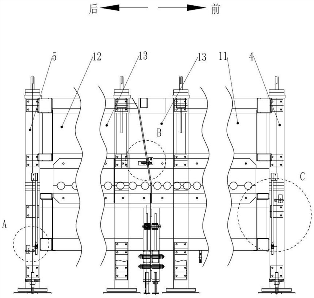
like figure 1 As shown, the current furnace body lifting system is to install the upper limit travel switch SQ1 and the lower limit travel switch SQ2 on one side of each furnace body section to control the limit of the furnace body section lifting, but each furnace body section of this design Both need to install two limit switches, which increases the cost

Method used


Image

  • Sequential lifting system of furnace bodies and control method thereof
  • Sequential lifting system of furnace bodies and control method thereof
  • Sequential lifting system of furnace bodies and control method thereof

Examples


Embodiment Construction

[0060] Embodiments of the present invention are described in detail below, examples of which are shown in the drawings, wherein the same or similar reference numerals designate the same or similar elements or elements having the same or similar functions throughout. The embodiments described below by referring to the figures are exemplary only for explaining the present invention and should not be construed as limiting the present invention.

[0061] In describing the present invention, it should be understood that the terms "center", "longitudinal", "transverse", "length", "width", "thickness", "upper", "lower", "left", " The orientation or positional relationship indicated by "right", "vertical", "horizontal", "top", "bottom", "inner", "outer", "axial", "radial", "circumferential" is Based on the orientation or positional relationship shown in the drawings, it is only for the convenience of describing the present invention and simplifying the description, and does not indica...


PUM


Abstract

The invention discloses a sequential lifting system of furnace bodies. A first limiting switch and a first touch block are arranged between a first furnace body and a rack; a second limiting switch and a second touch block are arranged between a second furnace body and the rack; intermediate switch groups are fixedly mounted between the first furnace body and an adjacent intermediate furnace body,adjacent two intermediate furnace bodies and the second furnace body and the adjacent intermediate furnace body; a first module is controlled by a first limiting switch to ascend the first furnace body, a second module controls the second furnace body to descend through a second limiting switch, and the intermediate modules separately control the first furnace body provided with the intermediatelimiting switch or the intermediate furnace body to descend and the next intermediate furnace body or the second furnace body to ascend through corresponding intermediate limiting switches. Compared with an existing furnace body lifting system, the sequential lifting system of furnace bodies is only provided with one limiting switch between adjacent two furnace bodies, so that the cost is lowered.

Description

technical field [0001] The invention relates to the technical field of glass heating furnace bodies, in particular to a furnace body sequential lifting system and a control method thereof. Background technique [0002] The principle of the glass physical tempering method is to heat the glass to a suitable temperature and then cool it rapidly, so that the glass surface shrinks sharply and generates compressive stress, while the middle layer of the glass cools slowly, and it is too late to shrink, so the tensile stress is formed, so that the glass obtains higher strength. . Generally speaking, the higher the cooling intensity, the greater the glass strength. In the tempering process of glass, heating and cooling are the most critical and important links, so a furnace body is needed, and the glass is transported by rollers in the furnace body, and is heated or cooled during the transportation process. [0003] In order to facilitate installation and / or maintenance, the curren...

Claims


Application Information

Patent Timeline
Patent Type & Authority Applications(China)
IPC IPC(8): B66F11/00B66F13/00
CPCB66F11/00B66F13/00
Inventor 杨杰林少琪刘仿华黄亮东
Owner SOOS (GUANGDONG) GLASS TECH CO LTD
Learn More