Multifunctional intelligent rod system based on high-speed wireless communication and installation method thereof

A high-speed wireless communication and wireless communication technology, applied in the multi-functional smart pole system and its installation field, can solve the problems of mixed strong and weak electric cables, easily interfered with communication, low safety factor, etc. Risk of cable wear and effect of reducing system cost

Pending Publication Date: 2020-10-13
航天科工通信技术研究院有限责任公司
View PDF0 Cites 2 Cited by
  • Summary
  • Abstract
  • Description
  • Claims
  • Application Information

AI Technical Summary

Problems solved by technology

Since the equipment also needs to use power supply cables, strong and weak electric cables are mixed in the cavity inside the rod. Once the cables are worn out and the conductors are exposed, it will cause communication interruption or leakage
Therefore, the traditional method has high installation cost, low safety factor, and communication is susceptible to interference

Method used


Image

  • Multifunctional intelligent rod system based on high-speed wireless communication and installation method thereof
  • Multifunctional intelligent rod system based on high-speed wireless communication and installation method thereof
  • Multifunctional intelligent rod system based on high-speed wireless communication and installation method thereof

Examples


specific Embodiment 1

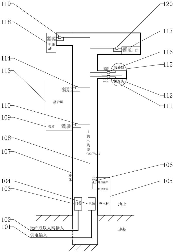
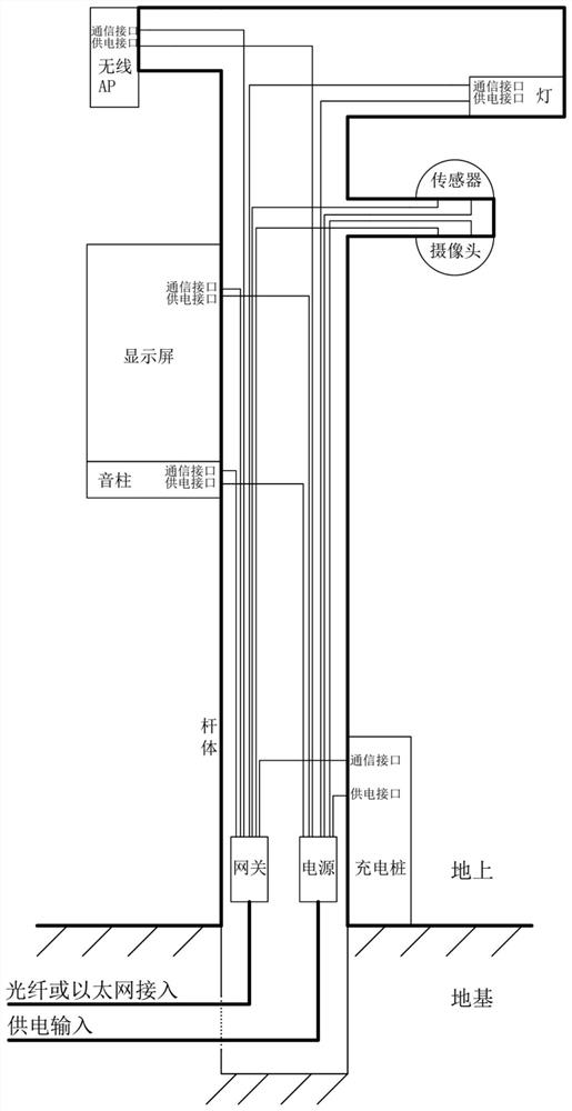
[0041] combine figure 1 , the present invention refers to a multifunctional smart pole system based on high-speed wireless communication, the multifunctional smart pole system includes a pole body, a gateway, a power supply, a wireless communication module, a main power supply cable, a mounting device and auxiliary materials.

[0042] The inside of the rod body is provided with a continuous cavity, and the rod body is provided with a mounting interface for installing a mounting device.

[0043] The gateway and the power supply are installed at the bottom of the continuous cavity, the gateway is connected to the communication access cable buried in the base, the input end of the power supply is connected to the power supply access cable buried in the base, and the power supply The output end of the main power supply cable is connected with the main power supply cable; the main power supply cable passes through the continuous cavity from the bottom of the rod body and leads out...

specific Embodiment 2

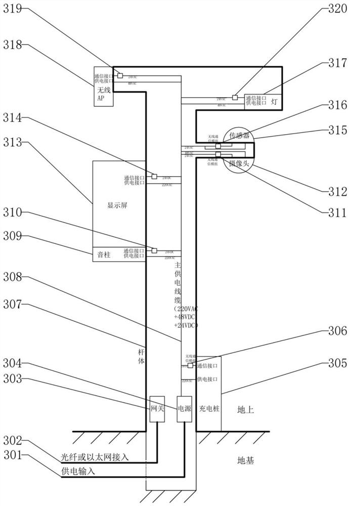
[0072] Combine below figure 1 and image 3 The three examples in the above-mentioned structure of the smart bar system are described.

example 1

[0074] The system consists of rod body 107, gateway 103, power supply 104, wireless communication modules 106, 110, 114, 111, 116, 119, 120, main power supply cable 108, mounting equipment 105, 109, 113, 112, 115, 117, 118 and accessories. The mounted device includes a light 117 , a sensor 115 , a camera 112 , a display screen 113 , a sound post 109 , a wireless AP 118 , and a charging pile 105 .

[0075] Rod body 107: the height is 3 meters to 12 meters, and the shape of the rod body is not limited. The rod body 107 has an internal continuous cavity with a cross-sectional area of ​​no less than 80cm2 and a width of no less than 5cm at the narrowest point. The bottom of the rod body has a hatch that can be opened and closed.

[0076] Power supply 104: It consists of a group of air switches, which are respectively used as the main power supply switch, the charging pile power supply switch, and other equipment power supply switches, a total of 3. The input and output of the p...


PUM


Abstract

The invention discloses a multifunctional intelligent rod system based on high-speed wireless communication. The multifunctional intelligent rod system comprises a rod body, a gateway, a power supply,a wireless communication module, a main power supply cable, mounting equipment and auxiliary materials. According to the system disclosed in the invention, wireless communication is adopted to realize connection between the multifunctional intelligent pole-mounted device and the gateway, the installation cost is reduced, the system security is improved, and the risk that communication is interfered is reduced; besides, by reasonably setting the network configuration of the equipment, the mounting equipment and the corresponding wireless communication module are automatically accessed to the gateway to form a local area network after the power supply is turned on, so that the installation efficiency is improved, and the installation faults are reduced.

Description

technical field [0001] The invention relates to the technical field of multifunctional smart poles, in particular to a multifunctional smart pole system based on high-speed wireless communication and an installation method thereof. Background technique [0002] Multifunctional smart poles, also known as smart light poles, are generally composed of pole bodies, gateways, power supplies, cables, and mounting devices. The mounting devices need to communicate with the outside through the gateway. Mounted devices generally include lights, cameras, displays, sound columns, and wireless APs. [0003] combine figure 2 , The communication between the device mounted on the traditional multifunctional smart pole and the gateway generally adopts wired communication methods, including RS485, Ethernet, etc. Therefore, the traditional smart bar must first install the communication cable in the cavity of the bar body before installing the equipment, and a clip must be made in the bar body...

Claims


Application Information

Patent Timeline
Patent Type & Authority Applications(China)
IPC IPC(8): H04Q1/02H04Q1/04H04Q1/06F21V21/10F21Y115/10
CPCF21V21/10F21Y2115/10H04Q1/02H04Q1/04H04Q1/06
Inventor 胡彦胜黄泽刚张启陈自然
Owner 航天科工通信技术研究院有限责任公司
Why Eureka
Try Eureka