LED aviation warning light with fault detection

a technology of aviation warning light and fault detection, which is applied in the direction of identification means, instruments, transportation and packaging, etc., can solve the problems of inconvenient operation, failure of any individual led to extinguish the entire light, and relatively high power consumption of incandescent and strobe lamps, so as to reduce the likelihood of false failure indication and flexible configuration

Inactive Publication Date: 2007-08-30
WHELEN ENGINEERING COMPANY
View PDF18 Cites 68 Cited by
  • Summary
  • Abstract
  • Description
  • Claims
  • Application Information

AI Technical Summary

Benefits of technology

[0010] Failure detection and failure mode actions are defined by program steps taken by firmware running in the microcontroller. For example, the microcontroller firmware can be configured to compensate for noise or spurious signals in the warning light to reduce the likelihood of false failure indications. Failure mode of the warning signal light is flexibly configurable by modification of the firmware. Examples of failure mode actions are shutting off the LEDs, changing the pattern of inputs to the bank driver circuits or generating a local failure indication or remotely detectable failure signal.

Problems solved by technology

Incandescent and strobe lamps suffer from relatively high power consumption and relatively short service life.
Strobe and incandescent light sources typically employ a single light source, making failure of that light source readily apparent upon inspection.
If all of the LEDs are arranged in series, failure of any individual LED would extinguish the entire light.
However, partial failure of an aircraft warning light may result in a light that fails to meet the requirements of the relevant regulation, while appearing to function normally to the typical observer / inspector.

Method used


Image

  • LED aviation warning light with fault detection
  • LED aviation warning light with fault detection
  • LED aviation warning light with fault detection

Examples


Embodiment Construction

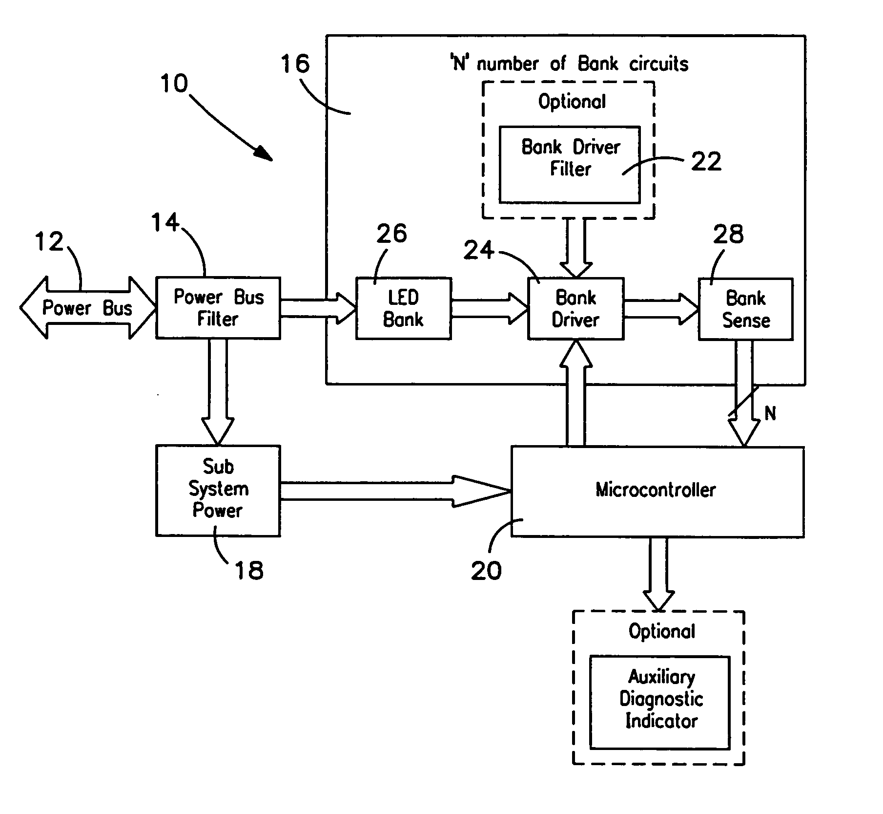
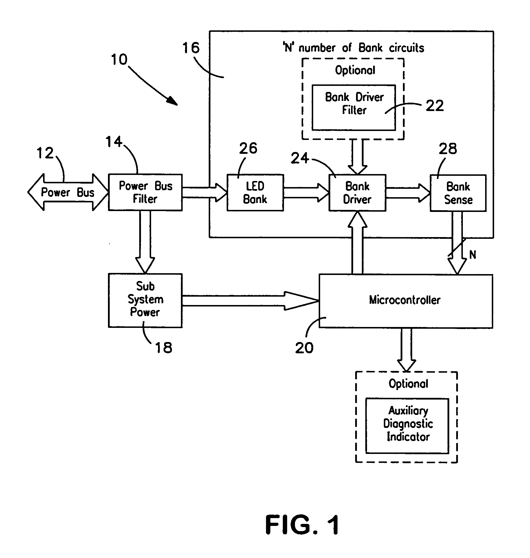
[0016] A preferred embodiment of an LED aviation warning light will now be described with reference to FIGS. 1-5, wherein like numbers refer to similar parts. FIG. 1 is a functional block diagram of an exemplary LED aviation warning light 10 according to aspects of the present invention. The LED aviation warning light 10 is connected to a power bus 12 of an aircraft through a power bus filter 14. Filtered electrical power is delivered to a “N” LED bank circuits 16, one for each series bank or branch of LEDs in the warning light. Electrical power is also delivered to a subsystem power circuit 18 that produces regulated low voltages (5VDC, 8VDC) for use by the microcontroller 20 and associated circuitry.

[0017] Each bank circuit 16 may include a bank filter 22. Filtering between the electrical system and the aviation warning light 10 and / or bank circuits 16 protects the warning light from voltage spikes in the aircraft electrical system and also prevents noise from the warning light f...


PUM


Abstract

An embodiment of an LED warning light includes a plurality of LED banks, each including a series of light emitting diodes. LED failure in one or more banks can result in a warning light that appears to be functional, but may not meet relevant standards for light production. The LED warning light monitors current flow through each LED bank to detect failure of an LED and produce a failure signal. The LED warning light includes a microcontroller programmed to evaluate the failure signals and take one or more pre-determined failure mode actions. Failure detection and failure mode actions are defined by program steps taken by firmware running in the microcontroller.

Description

BACKGROUND OF THE INVENTION [0001] 1. Field of the Invention [0002] The invention relates generally to external lighting for aircraft and more particularly to an LED aviation warning light incorporating redundancy and fault detection features. [0003] 2. Description of the Related Art [0004] Civilian air traffic control agencies such as the FAA specify standards for aircraft external lighting. Aircraft operating at night in civilian airspace are required to display lights to attract the attention of other aircraft operating in the same airspace. These external aircraft lights include flashing anti-collision lights mounted on the aircraft's upper and lower fuselage, as well as position / navigation lights on the tail and the wing tips. The location, color, intensity and light radiation pattern for each particular light is typically specified by the relevant regulation. [0005] Aircraft external lighting have previously been provided by “strobe” lights or incandescent lamps. Incandescent ...

Claims


Application Information

Patent Timeline
Patent Type & Authority Applications(United States)
IPC IPC(8): G09F9/33G08B21/00B64D47/06
CPCH05B33/0884B60Q11/005H05B45/54
Inventor FREDERICKS, THOMAS M.LEMIEUX, KENNETH S.
Owner WHELEN ENGINEERING COMPANY
Why Eureka
Try Eureka