A wireless charging method and system for electric vehicles based on smart light poles

An electric vehicle and wireless charging technology, applied in electric vehicle charging technology, electric vehicles, charging stations, etc., can solve the problems of easy leakage or short circuit, unsatisfactory safety performance, waste of space, etc., and achieve good safety and stability. Effect

Active Publication Date: 2022-07-01
深圳联和智慧科技有限公司
View PDF0 Cites 0 Cited by
  • Summary
  • Abstract
  • Description
  • Claims
  • Application Information

AI Technical Summary

Problems solved by technology

In this method, firstly, the charging connector is exposed, which is prone to leakage or short circuit in rainy days, and the safety performance is not satisfactory; secondly, sufficient space is required for use, and the waste of space is serious

Method used


Image

  • A wireless charging method and system for electric vehicles based on smart light poles
  • A wireless charging method and system for electric vehicles based on smart light poles
  • A wireless charging method and system for electric vehicles based on smart light poles

Examples


Embodiment 1

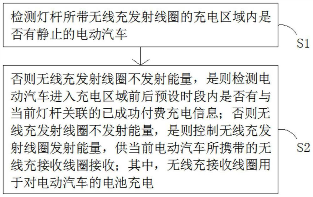
[0021] The embodiment of the present invention provides a wireless charging method for an electric vehicle based on a smart light pole, such as figure 1 shown, including the following steps:

[0022] Step S1: Detecting whether there is a stationary electric vehicle in the charging area of ​​the wireless charging and transmitting coil carried by the light pole.

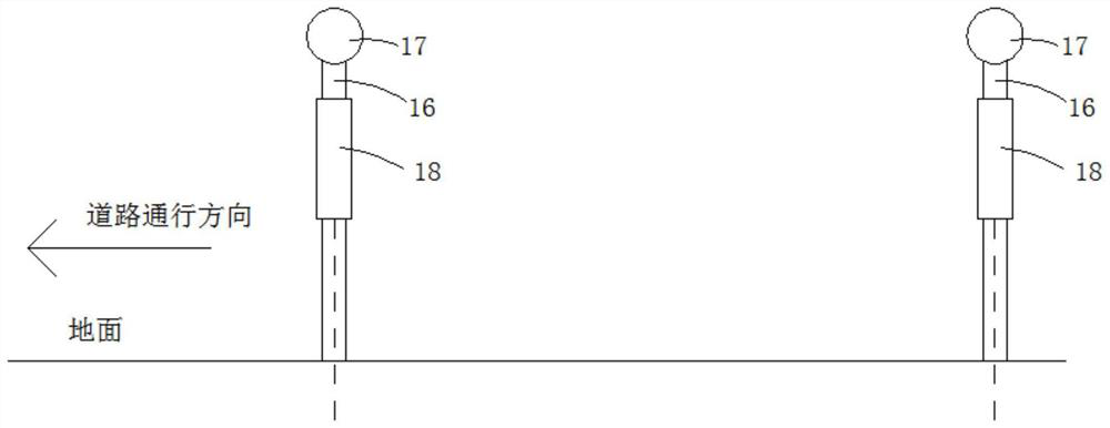
[0023] In this embodiment, before the step of detecting whether there is a stationary electric vehicle, two sets of detection rods are laterally arranged in the charging area of ​​the wireless charging and transmitting coil carried by the light pole; A rubber head contacting the bottom of the electric vehicle is fixed; the side surface of the detection rod is also fixed with an inclination switch whose detection end faces directly below. Specifically, when an electric vehicle enters the charging area of ​​the wireless charging and transmitting coil carried by the light pole, the detection pole will be tilted downward ...

Embodiment 2

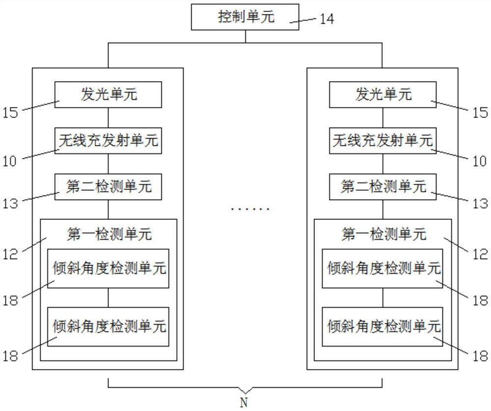
[0031] An embodiment of the present invention provides a wireless charging system for an electric vehicle based on a smart light pole, and a wireless charging method for an electric vehicle based on a smart light pole provided in Embodiment 1, such as Figure 2-Figure 3 shown, the system includes:

[0032] The wireless charging and transmitting unit 10 is arranged on the light pole;

[0033] A wireless charging and receiving unit (not shown in the figure), which is installed on the electric vehicle;

[0034] The first detection unit 12 is used to detect whether there is a stationary electric vehicle in the charging area of ​​the wireless charging and transmitting unit 10 carried by the light pole;

[0035] The second detection unit 13 is used to detect whether there is successfully paid charging information associated with the current light pole within a preset time period before and after the electric vehicle enters the charging area;

[0036] The control unit 14 is used to...


PUM


Abstract

The invention relates to a wireless charging method and system for an electric vehicle based on a smart light pole. The method detects whether there is a stationary electric vehicle in the charging area of ​​the wireless charging and transmitting coil carried by the light pole, otherwise the wireless charging and transmitting coil does not transmit energy, If it is, it will detect whether there is successful paid charging information associated with the current light pole within the preset period before and after the electric vehicle enters the charging area; otherwise, the wireless charging and transmitting coil will not transmit energy, and if it is, it will control the wireless charging and transmitting coil to transmit energy for the current electric vehicle. The wireless charging and receiving coil carried by it is received, so that the owner of the electric vehicle can charge without getting off the car, saving time and effort, and there is no exposed charging connector, which is not disturbed by the weather, and has good safety and stability. At the same time, the same range Multiple electric cars inside can be charged in turn under a light pole without wasting space.

Description

technical field [0001] The present invention relates to the technical field of vehicle charging, and more particularly, to a method and system for wireless charging of electric vehicles based on smart light poles. Background technique [0002] Electric vehicles refer to vehicles powered by on-board power, which are more environmentally friendly than fuel vehicles. However, when using it, how to charge it in time to ensure good battery life has become a key consideration. Now most of them are looking for specific sites to install batches of charging piles, divide charging parking spaces, and charge electric vehicles through wired means. In this method, one is that the charging connector is exposed, and it is prone to leakage or short circuit in rainy days, and the safety performance is not satisfactory. SUMMARY OF THE INVENTION [0003] The technical problem to be solved by the present invention is to provide a wireless charging method for an electric vehicle based on a s...

Claims


Application Information

Patent Timeline
Patent Type & Authority Patents(China)
IPC IPC(8): B60L53/126B60L53/66H02J50/10H02J50/80
CPCB60L53/126B60L53/665H02J50/10H02J50/80Y02T90/16
Inventor 杨海赖晓俊吴剑平唐盼王鹏林海荣
Owner 深圳联和智慧科技有限公司
Why Eureka
Try Eureka