Crane Energy Storage Monitoring and Scheduling System and Its Scheduling Method
A dispatching system and dispatching method technology, which is applied in the field of hoisting machinery, can solve problems such as poor reliability, influence on power generation, and low safety, and achieve the effects of avoiding overcharging, eliminating power generation hysteresis, and ensuring power generation
- Summary
- Abstract
- Description
- Claims
- Application Information
AI Technical Summary
Problems solved by technology
Method used
Image
Examples
no. 1 example
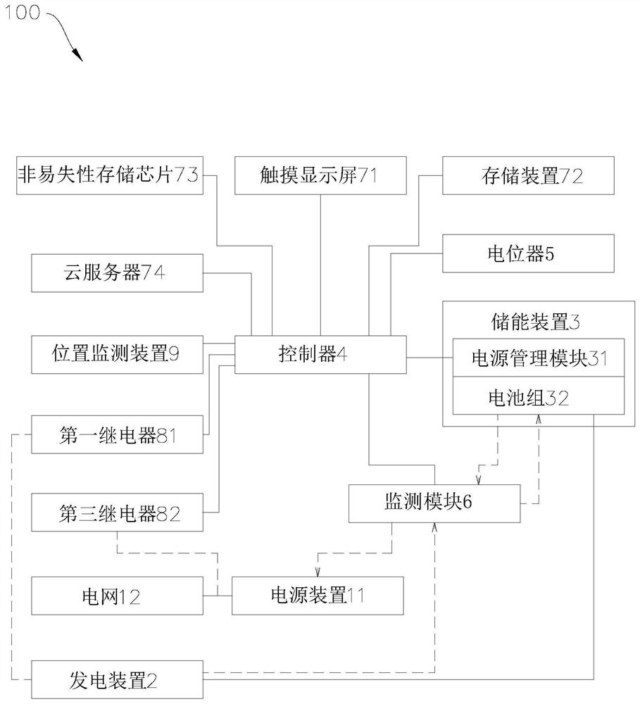
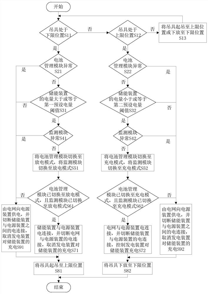
[0034] refer to figure 1 , the crane energy storage monitoring and dispatching system 100 includes a crane, a power generation device 2, an energy storage device 3, a controller 4, a potentiometer 5, a monitoring module 6, a touch screen 71, a storage device 72, a non-volatile memory chip 73 and a cloud server74. The crane includes a frame, a drive unit, a spreader and a power supply device 11, and the drive unit and the spreader are all arranged on the frame. The drive unit is used to drive the spreader to move, for example, drive the spreader to lift (that is, control the spreader to move up), drive the spreader to lower (that is, control the tool to move down); in addition, the drive unit can also control the frame To move, for example, when the crane is a gantry crane, the drive unit can drive the frame to move along the track, and can also drive the traverse mechanism of the frame to drive the spreader to move in a horizontal direction perpendicular to the extending dire...
no. 2 example
[0045] The difference between this embodiment and the first embodiment of the crane energy storage monitoring and dispatching system lies in:
[0046] In this embodiment, a second relay is used to replace the first relay 81 and the electromagnetic clutch. Specifically, the first coil terminal of the second relay is electrically connected to the third I / O output terminal of the controller 4, and the first coil terminal of the second relay is electrically connected to the third I / O output terminal of the controller 4. One contact terminal is electrically connected to the power generating device 2 , and the second contact terminal of the second relay is electrically connected to the energy storage device 3 . When the spreader is in the lifting state, the controller 4 can control the second relay to be in the off state, thereby preventing the power generation device 2 from charging the energy storage device 3 to protect the energy storage device 3; when the spreader is in the lower...
PUM
 Abstract
Description
Claims
Application Information
 - R&D
- Intellectual Property
- Life Sciences
- Materials
- Tech Scout
- Unparalleled Data Quality
- Higher Quality Content
- 60% Fewer Hallucinations
Browse by: Latest US Patents, China's latest patents, Technical Efficacy Thesaurus, Application Domain, Technology Topic, Popular Technical Reports.
© 2025 PatSnap. All rights reserved.Legal|Privacy policy|Modern Slavery Act Transparency Statement|Sitemap|About US| Contact US: help@patsnap.com


