Vehicular charging/discharging device
A charging and discharging device and vehicle technology, applied in circuit devices, battery circuit devices, electric vehicle charging technology, etc., can solve problems such as user falls
- Summary
- Abstract
- Description
- Claims
- Application Information
AI Technical Summary
Problems solved by technology
Method used
Image
Examples
Embodiment approach 1
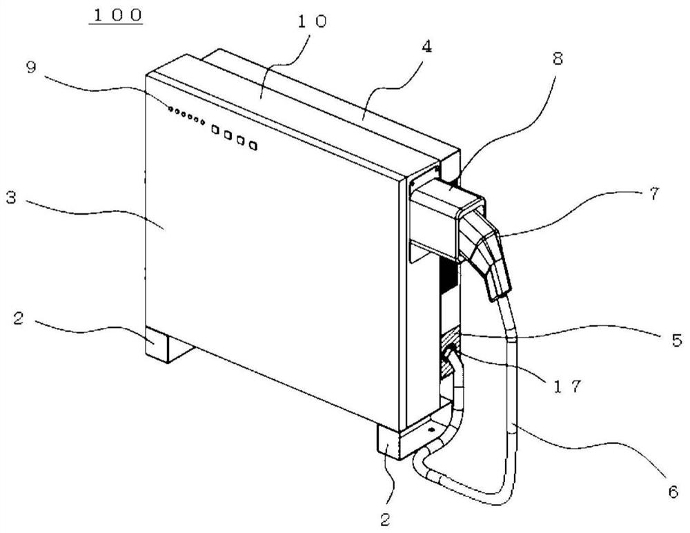
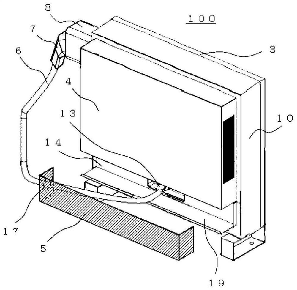
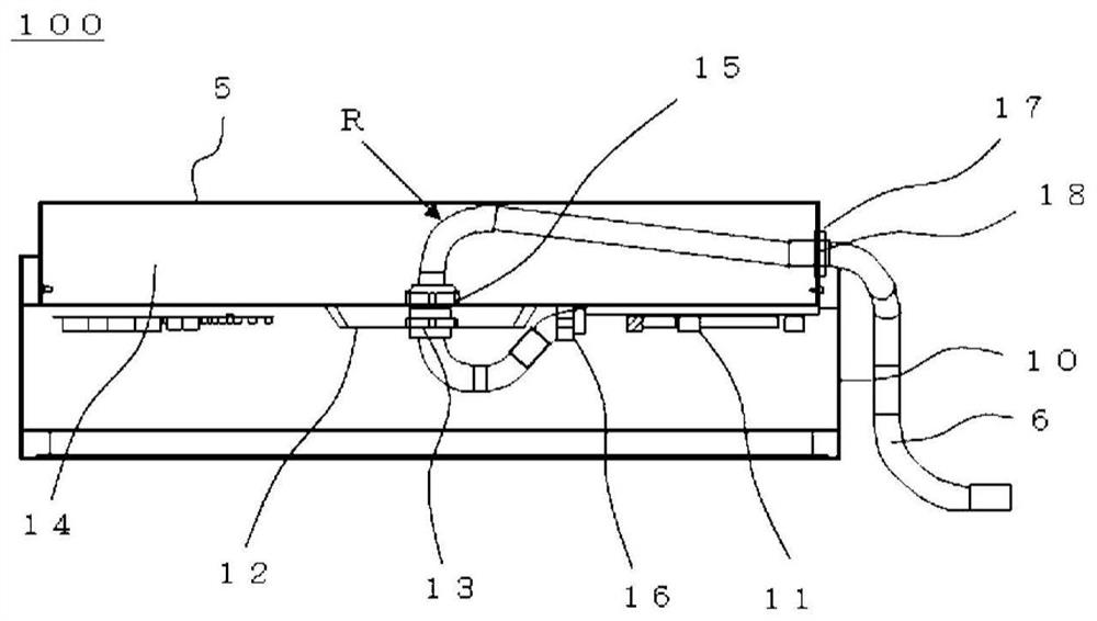
[0028] The configuration of the vehicle charge and discharge device in Embodiment 1 of the present invention will be described. exist figure 1 Among them, the vehicle charging and discharging device 100 has a box-shaped case 10, a bottom base 2, a front panel 3, a rear cover 4, a cable cover 5, a cable 6, a connector 7, a connector holder 8, and an operation part 9. .
[0029] Two bottom bases 2 are provided on the bottom of the case 10 and are used to fix the vehicle charging and discharging device 100 to an installation surface such as the ground. In addition, as long as the bottom surface base 2 can fix the vehicle charge-discharge device 100 on the installation surface, it is not limited to two, and any number may be installed.
[0030] The front panel 3 is installed to cover the front portion of the housing 10 . The operation unit 9 is provided on the front panel 3 , and can be operated by the user to operate the vehicle charge-discharge device 100 , stop the operation...
Embodiment approach 2
[0054] use Figure 6 , the vehicle charge and discharge device according to Embodiment 2 of the present invention will be described. In addition, in Figure 6 in, with Figure 1 to Figure 5 The same reference numerals indicate the same or corresponding parts. The vehicle charging / discharging device 100 according to the first embodiment has the rear cover 4 on the upper rear surface of the case 10, and has the member 19 and the cable cover 5 on the lower side of the rear cover 4. In contrast, the vehicle charging and discharging device 100 according to the second embodiment The charging and discharging device 200 has a rear cover 21 at the lower rear portion of the case 20 and has a member 23 and a cable cover 22 at the upper side of the rear cover 21 . In addition, since the structure other than the above is the same as that of Embodiment 1, how to route the cable 6 and how to deal with the case where an electric vehicle (not shown) is parked on the left side of the vehicle...
Embodiment approach 3
[0057] use Figure 7 , the vehicle charge and discharge device according to Embodiment 3 of the present invention will be described. In addition, in Figure 7 in, with Figure 1 to Figure 6 The same reference numerals indicate the same or corresponding parts. The vehicle charging and discharging device 100 according to Embodiment 1 is provided such that the rear cover 4 is provided on the upper rear surface of the housing 10 , and the member 19 and the cable cover 5 are provided on the lower side of the rear cover 4 , and the member 19 covers the rear surface of the housing 10 . On the lower bottom part, the cable cover 5 covers the left and right side parts and the rear part of the lower rear part of the case 10 when viewed from the front. The back lower part of the body 30 has a back cover 31, and has a part 33 and a cable cover 32 on the upper side of the back cover 31, the part 33 covers the back part of the upper back part of the housing 30, and the cable cover 32 cove...
PUM
 Abstract
Description
Claims
Application Information
 - R&D
- Intellectual Property
- Life Sciences
- Materials
- Tech Scout
- Unparalleled Data Quality
- Higher Quality Content
- 60% Fewer Hallucinations
Browse by: Latest US Patents, China's latest patents, Technical Efficacy Thesaurus, Application Domain, Technology Topic, Popular Technical Reports.
© 2025 PatSnap. All rights reserved.Legal|Privacy policy|Modern Slavery Act Transparency Statement|Sitemap|About US| Contact US: help@patsnap.com


