Lever type connector

A connector and rod-type technology, applied in the direction of connection, parts and electrical components of the connecting device, etc., can solve the problems of increased fitting resistance and difficult fitting of the connector, and achieve the effect of avoiding damage.

Active Publication Date: 2012-05-30
TYCO ELECTRONICS JAPAN GK
View PDF5 Cites 0 Cited by
  • Summary
  • Abstract
  • Description
  • Claims
  • Application Information

AI Technical Summary

Problems solved by technology

[0002] In the case of fitting many connectors with each other, since the fitting resistance generated between the two contacts increases, it becomes difficult to push the connectors to each other directly by hand

Method used


Image

  • Lever type connector
  • Lever type connector
  • Lever type connector

Examples


Embodiment Construction

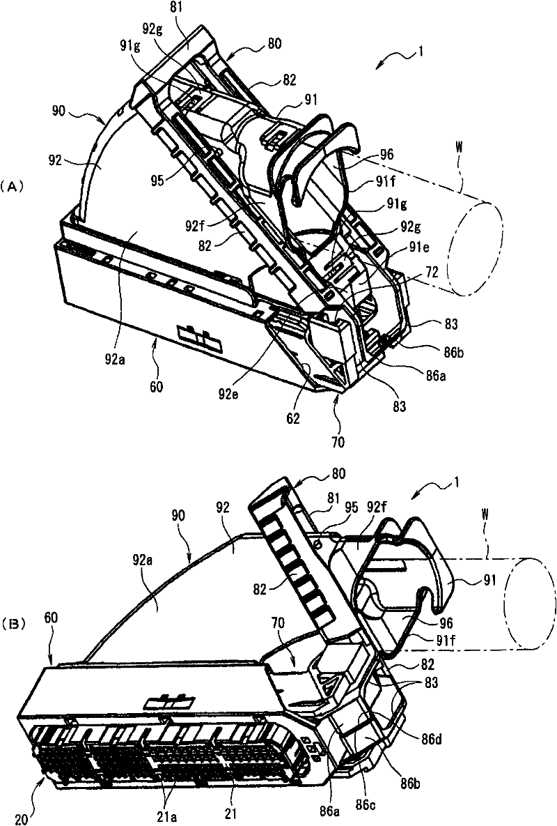
[0057] Next, embodiments of the present invention will be described with reference to the drawings. figure 1 (A) is a perspective view seen from the back side, and (B) is a perspective view seen from the front side which shows the lever type connector of this invention.

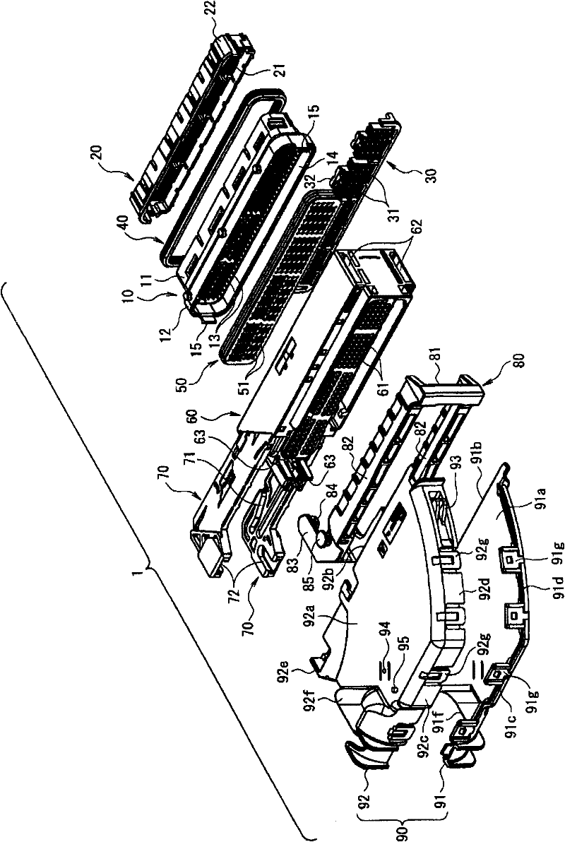
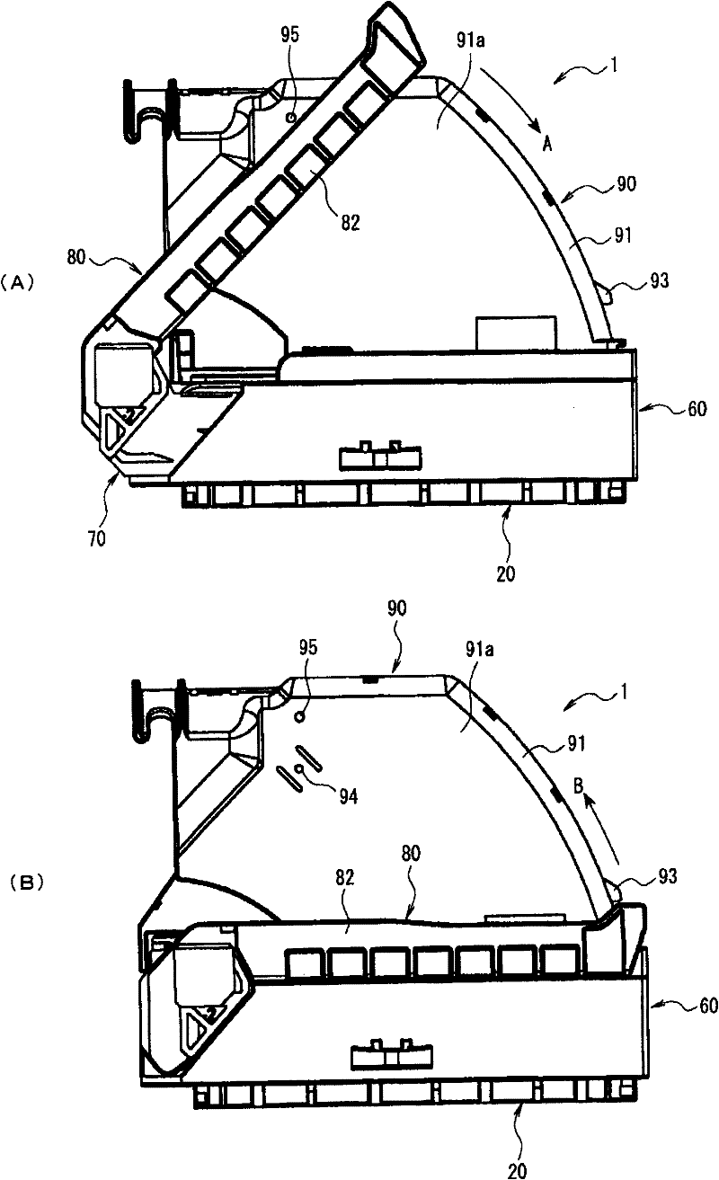
[0058] figure 2 yes figure 1 An exploded perspective view of the rod connector. image 3 show figure 1 (A) is the state when the lever is at the disengaged position, and (B) shows the state where the lever is at the mating position. Figure 4 show figure 1 The rod connector of , the rod connector showing the state where the rod is in the separated position, (A) is a cross-sectional view obtained by cutting the rod and slider, (B) is a cross-sectional view along line 4B-4B of (A) . Figure 5 show from figure 1 (A) is a perspective view viewed from the front side, (B) is a rear view, and (C) is an enlarged view of a portion indicated by arrow 5C in (B) of the lever connector shown without the wire ...


PUM


Abstract

A lever type connector in which, when a mating connector is fitted on the base sides of arm sections of a lever in a prying manner, damage on a contact provided on the mating connector is prevented. In the lever type connector (1), the lever (80) has an operation section (81) and the pair of arm sections (82) extending from opposite ends of the operation section (81), where the lever (80) is attached, on the base sides of the arm sections (82), to a housing (60) or a wire cover (90). On the base sides of the pair of arm sections (82) of the lever (80) are provided a pair of wall sections (86a, 86b) extending from the base sides and having top edges (86c, 86d) facing each other.

Description

technical field [0001] The present invention relates to a lever type connector for reducing fitting (separating) operation force. Background technique [0002] When many connectors are fitted to each other, since the fitting resistance generated between the two contacts increases, it becomes difficult to push and fit the connectors to each other directly by hand. Therefore, various so-called lever-type connectors utilizing a double-force mechanism for reducing a fitting (separating) operation force have been proposed. [0003] As an existing such lever connector, for example, known Figure 13 and Figure 14 The connector shown (refer to Patent Document 1). Figure 13 It is a cross-sectional view of an example of a conventional lever connector. Figure 14 yes Figure 13 Explanatory drawing of the wire cover and rod of the rod connector shown. [0004] Figure 13 The illustrated lever connector 101 is configured by fitting a corresponding connector 150 , and includes a case...

Claims


Application Information

Patent Timeline
Patent Type & Authority Patents(China)
IPC IPC(8): H01R13/629
CPCH01R13/62938H01R13/62977H01R13/62911
Inventor 小宫山隆一酒卷一诚
Owner TYCO ELECTRONICS JAPAN GK
Why Eureka
Try Eureka