Electric wire laying head device, and electric wire laying apparatus

A wire routing and head technology, applied in the direction of electrical components, manufacturing wiring harnesses, electrical components, etc., can solve problems such as wire floating easily

Inactive Publication Date: 2013-03-13
SUMITOMO WIRING SYST LTD
View PDF2 Cites 0 Cited by
  • Summary
  • Abstract
  • Description
  • Claims
  • Application Information

AI Technical Summary

Problems solved by technology

Therefore, when the wire is wound around the rib-shaped portion protruding from the wiring board and wired, the portion of the wire that rises sharply from the wiring board is wound around the rib-shaped portion, and the wire is likely to float.

Method used


Image

  • Electric wire laying head device, and electric wire laying apparatus
  • Electric wire laying head device, and electric wire laying apparatus
  • Electric wire laying head device, and electric wire laying apparatus

Examples


no. 1 Embodiment approach

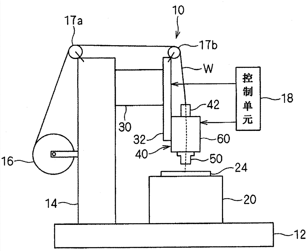
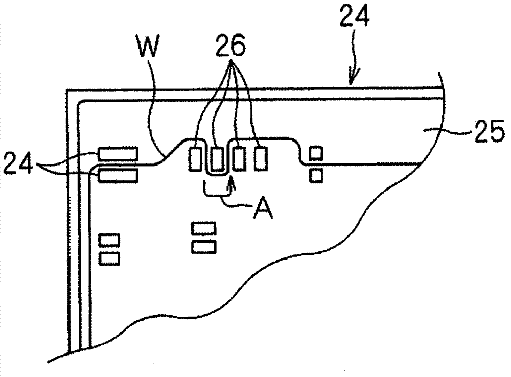
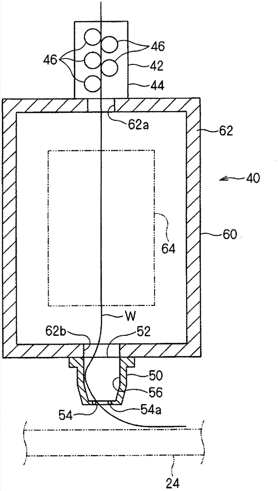
[0040] Hereinafter, the wire routing device and the wire routing head unit according to the first embodiment will be described. In the first embodiment, the form related to the basic concept will be described. figure 1 It is an explanatory diagram showing the whole of the electric wire wiring device 10, figure 2 is a schematic plan view showing a part of a wiring board as a wiring object, image 3 It is a schematic cross-sectional view showing the head unit 40 for wire routing, Figure 4 is a schematic sectional view showing the head 50, Figure 5 It is a schematic plan view showing the head 50 . exist Figure 4 and Figure 5 In , the state of the electric wire W in the wiring operation is shown.

[0041] This wire routing device 10 includes a wire routing head unit 40 , a wiring board fixing portion 20 , and a wire driving mechanism portion 30 .

[0042] The wiring board fixing portion 20 constitutes a wiring object holding portion for holding a wiring board 24 as a w...

no. 2 Embodiment approach

[0070] Figure 8 It is a schematic cross-sectional view showing the wire routing head unit 140 according to the second embodiment. In addition, in the following description, the same code|symbol is attached|subjected to the same component as the component already demonstrated, and the description is abbreviate|omitted.

[0071] This wire routing head device 140 has a wire crease removal unit 42 , a head 50 , and a wire delivery unit 160 . In this embodiment, a specific configuration example of the electric wire delivery unit 160 will be described.

[0072]The electric wire sending part 160 has the outer casing 162 which has a substantially basket shape, and the electric wire feeding mechanism part 164 provided in the casing 162. As shown in FIG. In the housing 162, a stepped portion 162c facing upstream in the feeding direction of the wire W is formed on the front side (upstream side in the feeding direction of the wire W) of the opening 162b located on the head 50 side. Ot...

no. 3 Embodiment approach

[0094] Figure 11 It is a schematic cross-sectional view showing the wire routing head unit 240 according to the third embodiment.

[0095] This wire routing head device 240 has a wire crease removal part 42 , a head part 50 , and a wire delivery part 260 . In this embodiment, a specific configuration example of the electric wire delivery unit 260 will be described.

[0096] The electric wire delivery part 260 has the casing 62 which has a substantially basket shape, and the electric wire feeding mechanism part 264 provided in the casing 62. As shown in FIG. Inside the casing 62 is provided an internal nozzle 161 having the same structure as the internal nozzle described in the second embodiment.

[0097] The wire feeding mechanism part 264 has a chuck part 266 , a chuck reciprocating drive part 268 , and a chuck drive part 270 .

[0098] The chuck portion 266 has a pair of chuck pieces 266a, and is configured such that the wire W can be clamped by moving the pair of chuck ...


PUM


Abstract

Disclosed is an electric wire laying head device capable of changing easily the deriving direction of an electric wire from a head unit and suppressing more reliably the float of the electric wire when the electric wire is laid.  The electric wire laying head device for laying an electric wire on a subject to be layed, comprises a head unit arranged to face the subject, and an electric wire let-off unit capable of letting off the electric wire toward the head unit.  The head unit has a derivation port formed with a larger inner diameter than the outer diameter of the electric wire, and a bend allowing space formed on this side of the derivation port for allowing the bend of the electric wire.

Description

technical field [0001] The present invention relates to a technology for manufacturing circuit elements having wires laid therein, such as internal wiring structures of devices such as electrical junction boxes and automatic transmissions for vehicles. Background technique [0002] In the past, as the head structure of the wire wiring device, there are the following structures: a structure in which the electric wire is supplied through a straight hole (refer to the prior art of Patent Document 1), and a structure in which the electric wire is bent and guided outward by a guide roller (refer to the structure of the patent document 1). Prior Art, Patent Document 2) and the like. [0003] Patent Document 1: Japanese Publication No. 7-40260 [0004] Patent Document 2: Japanese Patent Application Laid-Open No. 10-22495 [0005] However, in the former prior art, the wires led out from the straight holes are bent with a relatively small bending radius and routed to the wiring boa...

Claims


Application Information

Patent Timeline
Patent Type & Authority Patents(China)
IPC IPC(8): H01B13/012H02G3/16
CPCH05K13/06
Inventor 服部充博大石明典谷德之菊地佑介
Owner SUMITOMO WIRING SYST LTD
Why Eureka
Try Eureka