A four-pipe heating unit recovery system and its control method

A technology of a recovery system and a control method, which is applied to the recovery system of a four-pipe heat unit and its control field, can solve the problems that cannot be realized, cannot accurately reflect the real-time demand of the unit, and infinitely adjust the temperature of the heat recovery outlet water, so as to solve the problem of speed lag. Effect

Active Publication Date: 2021-11-09
SHANDONG PEIRCE
View PDF5 Cites 0 Cited by
  • Summary
  • Abstract
  • Description
  • Claims
  • Application Information

AI Technical Summary

Problems solved by technology

However, the temperature sensor has hysteresis and cannot accurately reflect the real-time demand of the unit for the fan speed. Therefore, the fan speed is adjusted in sections according to the temperature. Although this method can realize the segmental adjustment of the condensing fan speed, but , but it is impossible to realize stepless regulation of heat recovery outlet water temperature

Method used


Image

  • A four-pipe heating unit recovery system and its control method
  • A four-pipe heating unit recovery system and its control method
  • A four-pipe heating unit recovery system and its control method

Examples


Embodiment 1

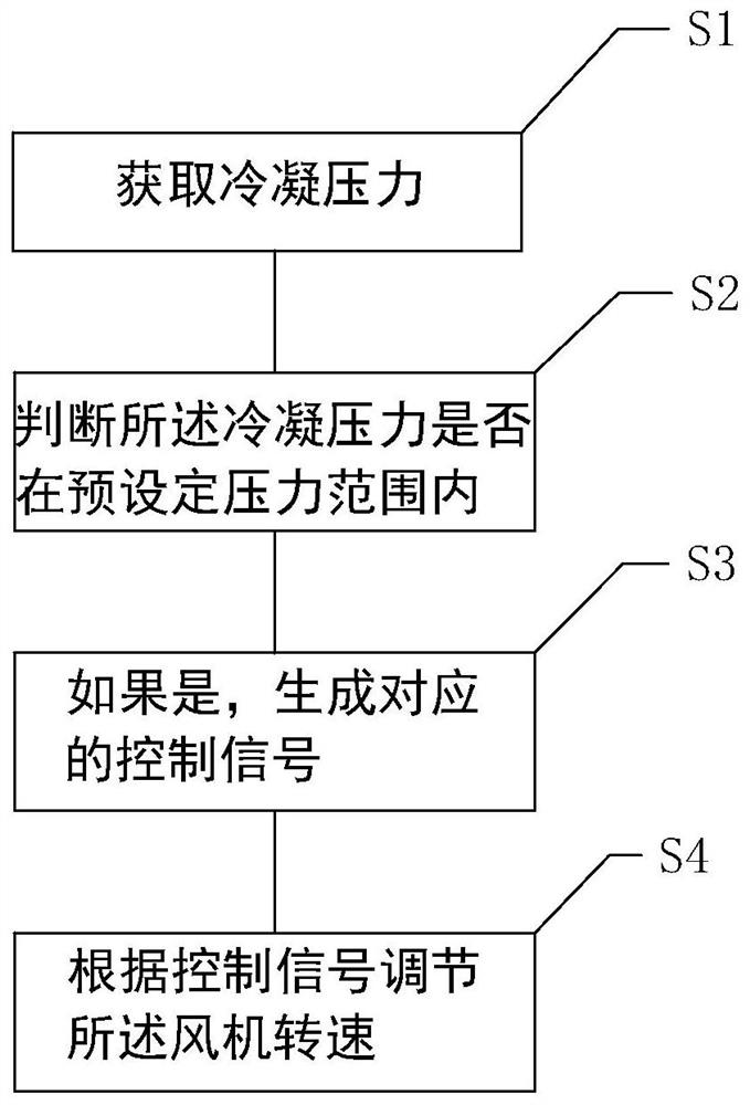
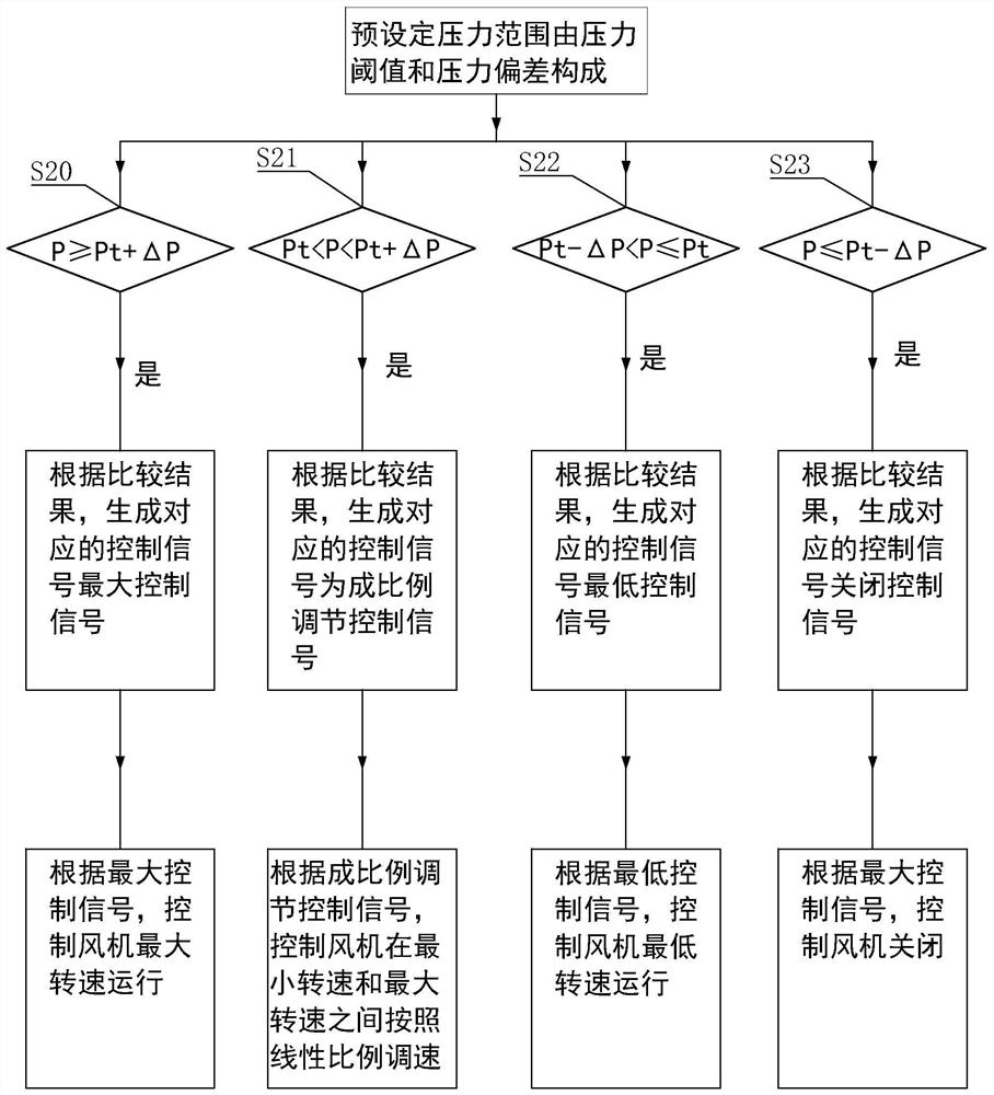
[0045] Such as figure 1 and figure 2 As shown, a control method of a four-pipe heating unit recovery system is based on a four-pipe heating unit recovery system. The system includes a fan and a plate heat exchanger, and a pressure sensor for detecting the condensation pressure is provided on the condensation outlet side of the plate heat exchanger;

[0046] The control method comprises the following steps:

[0047] Step S1, obtaining the condensation pressure;

[0048] Step S2, judging whether the condensing pressure is within a preset pressure range;

[0049] Step S3, if yes, generating a corresponding control signal;

[0050] Step S4, adjusting the fan speed according to the control signal.

[0051] By adopting the method of the present invention, the operating state of the unit is monitored in real time, and the speed of the fan is adjusted steplessly within a certain range, thereby realizing the purpose of heat recovery and outlet water temperature; the problem of lag...

Embodiment 2

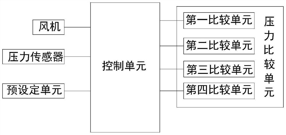
[0071] Such as image 3 As shown, a four-pipe heating unit recovery system includes a fan, a plate heat exchanger, a pressure sensor installed on the condensation outlet side of the plate heat exchanger to detect the condensation pressure, and a control unit electrically connected to the fan and the pressure sensor respectively ; Also includes a pressure comparison unit, the pressure comparison unit is used to judge whether the condensing pressure is within the preset pressure range; if so, generate a corresponding control signal, which is transmitted to the control unit; the control unit adjusts the fan steplessly according to the control signal Rotating speed. The control unit includes a fan speed controller, a frequency converter or a variable frequency drive, wherein the fan speed controller is used to detect the pressure signal, and output a DC voltage signal corresponding to 0-10V according to the pressure signal, wherein the frequency converter or variable frequency dri...


PUM


Abstract

The invention discloses a four-pipe heating unit recovery system and a control method thereof, and relates to the technical field of air conditioning, wherein the system includes a fan and a plate heat exchanger, and a pressure sensor for detecting condensation pressure is arranged on the condensation outlet side of the plate heat exchanger. It includes a control unit and a pressure comparison unit, the control unit is electrically connected to the fan and the pressure sensor respectively; the control method includes the following steps: obtaining the condensing pressure through the control unit; then judging whether the condensing pressure is within the preset pressure range; if yes, generating Corresponding control signal; the control unit adjusts the speed of the fan according to the control signal, so as to realize real-time monitoring of the operating state of the unit, steplessly adjust the speed of the fan within a certain range, and then realize the purpose of heat recovery outlet water temperature; solve the problem of condensing temperature in the prior art Adjust the fan speed lag problem.

Description

technical field [0001] The invention relates to the technical field of air conditioning, in particular to a recovery system of a four-pipe heating unit and a control method thereof. Background technique [0002] The four-pipe heat recovery control system is for the air-cooled chilled water (heat pump) four-pipe heat recovery unit to recover waste heat as a constant heat source for reheating during cooling operation. It does not need an energy storage water tank and can steplessly adjust the temperature of hot water to purify the air conditioner. In this mode, a stable cold source and heat source control scheme is provided at the same time. At present, the rotation speed of the condensing fan is adjusted in sections based on the detected ambient temperature and the temperature of the heat recovery outlet water, so as to achieve the purpose of segmentally controlling the condensation pressure and regulating the temperature of the heat recovery outlet water. However, the tempe...

Claims


Application Information

Patent Timeline
Patent Type & Authority Patents(China)
IPC IPC(8): F24F11/64F24F11/70F24F12/00F24F140/10
CPCF24F12/00F24F11/64F24F11/70F24F2140/10Y02B30/56
Inventor 吴松韩跃洲
Owner SHANDONG PEIRCE
Why Eureka
Try Eureka