Non-contact heart rate monitoring method and system

A heart rate monitoring, non-contact technology, used in pulse rate/heart rate measurement, diagnostic recording/measurement, medical science, etc., and can solve problems such as inability to calculate heart rate

Active Publication Date: 2021-04-13
HEFEI UNIV OF TECH
View PDF7 Cites 0 Cited by
  • Summary
  • Abstract
  • Description
  • Claims
  • Application Information

AI Technical Summary

Problems solved by technology

[0006] Aiming at the deficiencies of the prior art, the present invention provides a non-contact heart rate monitoring method and system, which solves the problem that data other than the frequency value corresponding to the maximum value of the frequency domain response cannot be fully utilized in the time domain signal and frequency domain signal. Technical issues with calculating heart rate

Method used


Image

  • Non-contact heart rate monitoring method and system
  • Non-contact heart rate monitoring method and system
  • Non-contact heart rate monitoring method and system

Examples


Embodiment 1

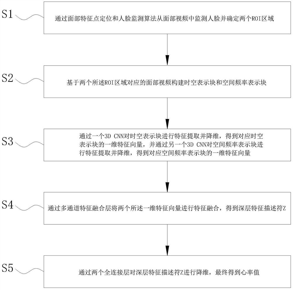
[0067]Such asFigure 1-2As shown, the present invention provides a non-contact heart rate monitoring method, which is performed by a computer, which includes S1-S5:

[0068]S1, the facial features and face monitoring algorithms are monitored from the face video and determine two ROI regions;

[0069]S2, a surface video constructs a block and a spatial frequency representation block based on the face video corresponding to the two ROI regions;

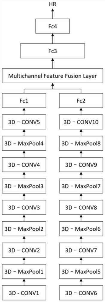
[0070]S3, characterized by a 3D CNN to characterize the time and space representation block, resulting in a one-dimensional vector vector of the corresponding time and space representing the block, and the spatial frequency representation block is characterized by another 3D CNN, and the corresponding spatial frequency is obtained. A generic vector representation of the block;

[0071]S4, two of the one-dimensional forming vectors are fused by multi-channel feature fusion layer to obtain a deep features descriptor z;

[0072]S5, through two full connecting l...

Embodiment 2

[0123]The present invention also provides a non-contact heart rate monitoring system, including a face monitoring module, a ROI region screening module, a time-space representation block generation module, a spatial frequency representation block generation module, a multi-channel feature fusion heart rate monitoring network module;

[0124]The face monitoring module is used to monitor the face in the face video, and monitor the coordinates of facial features;

[0125]The ROI region screening module is configured to screen two regions as the ROI region from the coordinates of the face feature points;

[0126]The time and space representation block generation module includes a time domain signal extracting unit and a time space block build unit; the time domain signal extracting unit is used to adjust the resolution of the facial video corresponding to the ROI region to hRoi1 * WRoi1 HoRoi2 * WRoi2 , Get the time domain signal of the nth pixel in the RGB color gamut space:

[0127]RMn = {PR(n, 1...


PUM


Abstract

The invention provides a non-contact heart rate monitoring method and system, and relates to the technical field of heart rate monitoring. Monitor the face from the facial video and determine two ROI areas through facial feature point positioning and face detection algorithms; then obtain the time domain signal of the nth pixel in the RGB color gamut space based on the facial video corresponding to the ROI area, and then based on Obtain the spatio-temporal representation block of the original facial video from the time domain signal; obtain the frequency domain signal by using fast Fourier transform and band-pass filter; obtain the spatial frequency representation block of the original facial video according to the frequency domain signal; and fused heart rate monitoring through multi-channel features The network extracts features and reduces dimensionality for spatiotemporal representation blocks and spatial frequency representation blocks, and calculates the heart rate value. It solves the technical problem that the prior art cannot make full use of data other than the frequency value corresponding to the maximum value of the frequency domain response in the time domain signal and the frequency domain signal to calculate the heart rate, and can effectively improve the accuracy of heart rate estimation.

Description

Technical field[0001]The present invention relates to the field of heart rate monitoring, and more particularly to a non-contact heart rate monitoring method and system.Background technique[0002]When monitoring the heart rate for infectious disease patients, non-contact monitoring methods can effectively avoid the risk of medical staff and the patient's infection, and reduce the risk of medical staff.[0003]The existing non-contact heart rate monitoring method is mostly monitoring based on visual image information technology, for example, patent No. 2015107410069 discloses a non-contact heart rate monitoring method, including: first acquiring the monitored face The video image data, identifies the face of the face in the image data, and calculates the regional image of the face of interest; re-enlarged the red and green component differential value of the image of interest to the time domain differential color change, and interested The differential amplification of the regional imag...

Claims


Application Information

Patent Timeline
Patent Type & Authority Patents(China)
IPC IPC(8): A61B5/024
CPCA61B5/024A61B5/72A61B5/7257A61B5/7267
Inventor 丁帅岳子杰柯震杨善林李霄剑欧阳波顾东晓
Owner HEFEI UNIV OF TECH
Why Eureka
Try Eureka