A multi-link connecting device with multi-angle adjustment and locking

A connecting device and multi-link technology, applied in the direction of connecting rod bearings, pivot connections, shafts and bearings, etc., can solve problems such as inconvenient installation, difficulty in installation and maintenance, and reduced bearing capacity of connecting rod structures, and achieve convenient installation, Easy disassembly, simple structure and operation

CN111853049BActive Publication Date: 2022-06-21JIANGSU WEIHANG AUTOMOBILE COMM TECH CO LTD
6 Cites 0 Cited by

Patent Information

Authority / Receiving Office
CN · China
Patent Type
Patents(China)
Current Assignee / Owner
Publication Date
2022-06-21

Smart Images

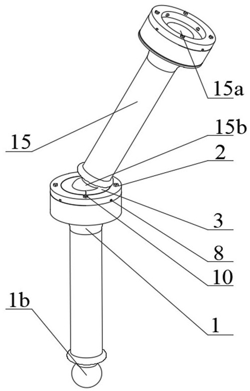
  • Figure 1
    Figure 1
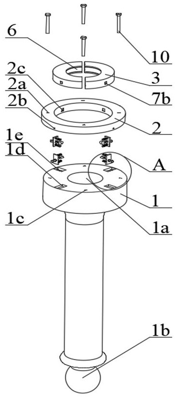
  • Figure 2
    Figure 2
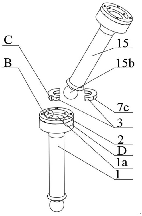
  • Figure 3
    Figure 3
Patent Text Reader

Abstract

The invention discloses a multi-angle adjustable and locked multi-link connecting device in mechanical equipment. The lower ends of the connecting rods are all ball heads, and the upper ends are cylindrical bosses. The center of the upper surface of the cylindrical boss of the first connecting rod is There is a first spherical groove with an inner diameter equal to the outer diameter of the second ball head of the second connecting rod, and the upper surface of the cylindrical boss is coaxially fixed with a connecting rod cover in the shape of a connecting ring, and the central hole of the connecting rod cover is coaxially tight. There is a ring-shaped bearing. The bearing is composed of two identical semi-annular bodies radially coupled. The middle of the bearing shell of each semi-annular body has a semi-circular arc-shaped groove in a semi-circular shape. The interior is equipped with permanent magnets, bearing springs and electromagnets from the inside to the outside. The two permanent magnets are radially magnetized and the magnetization directions are opposite; in the initial state, the two permanent magnets absorb and lock the second ball head, and the connecting rod needs to be adjusted When the angle is specified, the coil of the electromagnet is energized, and the two permanent magnets release the second ball head, so that the multi-angle adjustment of the multi-link structure is realized, and the disassembly is convenient.
Need to check novelty before this filing date? Find Prior Art

Description

technical field

[0001] The invention relates to a connecting device in mechanical equipment, in particular to a multi-link connecting device which can freely adjust the angle and be locked. Background technique

[0002] The connection devices in traditional mechanical equipment can be seen everywhere in daily life, such as computer brackets and the shaking mechanism of fans, but there are often a series of problems such as electrical failures and high costs. Although these common mechanisms can meet the needs of daily life, they often face problems such as overly complex mechanical structures, inconvenient installation, and complicated manual repair costs, especially for connection devices in heavy industries, such as excavators. Grabbing the head, etc., not only requires a flexible control mechanism but also requires a connection device to carry heavy objects.

[0003] At present, the connecting devices commonly used between connecting rods are divided into welding or trad...

Examples

Embodiment Construction

[0021] For ease of understanding, the spatial orientation of the present invention is now defined: see figure 1 , the second ball head 15b of the second connecting rod 15 is defined as "up", the position of the first ball head 1b of the first connecting rod 1 is "down", and the central axis direction of the first connecting rod 1 is defined as " Axial", the direction perpendicular to this is defined as "radial"; the axis of the central axis is defined as "inner", and the opposite direction is "outer".

[0022] see figure 1 , a multi-angle adjustment and locking multi-link connecting device of the present invention includes a plurality of connecting rods connected in series up and down, and the connecting parts of each two connecting rods are connected by a connecting rod cover 2 and a bearing 3, that is Connect the two connecting rods together with connecting rod cap 2 and bearing 3. figure 1 Taking only two links as an example, the connection structure and connection method...