Adjustable railing post

An adjustable, railing technology, applied in the direction of ships, dry docks, slipways, etc., can solve the problems of complex operation procedures, installation can not be carried out normally, error-prone, etc.

Inactive Publication Date: 2016-06-01
GUANGZHOU SHIPYARD INTERNATIONAL LTD
View PDF8 Cites 3 Cited by
  • Summary
  • Abstract
  • Description
  • Claims
  • Application Information

AI Technical Summary

Problems solved by technology

And the existing way of pulling safety fence has following defect: 1, if adopt the mode that upright column is welded on the fracture position of section / total section, also need electric welding to cooperate each time installation, when removing safety fence, also need gas cutting to cooperate , the operation procedure is too complicated; 2. If the directional clamping seat is used to lock the column, due to the various fracture forms of each segment / total segment, the fracture position of the plate has both vertical structure and horizontal structure. There are certain angled and directional clamping seats that need to be manufactured in various forms and in large quantities to meet the requirements of on-site use. It is also easy to make mistakes during sorting, resulting in subsequent installations that cannot be carried out normally and affect installation efficiency.

Method used


Image

  • Adjustable railing post
  • Adjustable railing post
  • Adjustable railing post

Examples


Embodiment Construction

[0023] The technical solutions of the present invention will be further described below in conjunction with the accompanying drawings and through specific implementation methods.

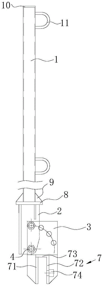
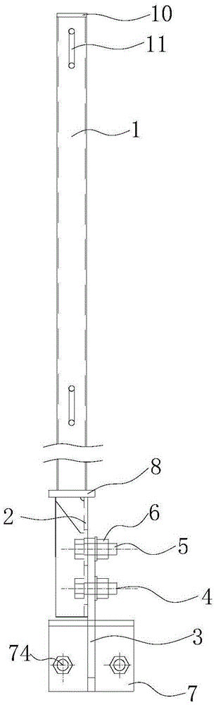
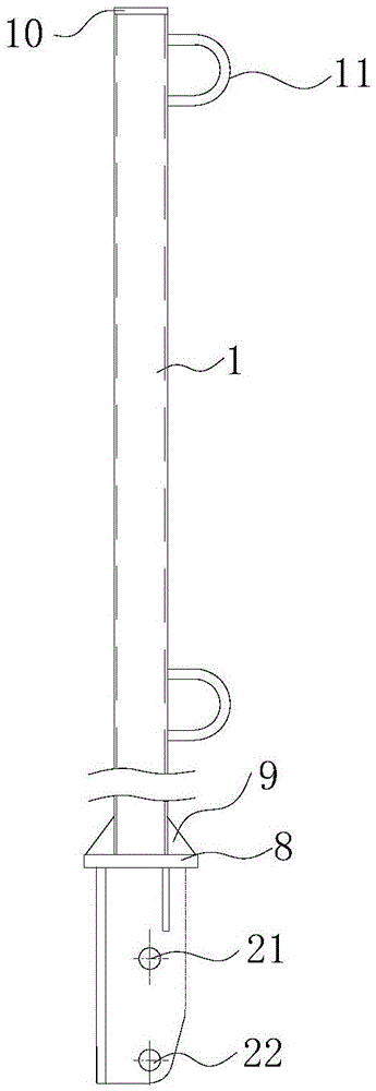
[0024] like Figures 1 to 4 As shown, in an embodiment of the present invention, an adjustable railing post includes a pole 1, one end of the pole 1 is provided with a connecting plate 2, and the connecting plate 2 is provided with first positioning holes 21 and a first rotating shaft at intervals along its length direction. Holes 22, the first positioning hole 21 is set adjacent to the vertical rod 1, and the adjusting plate 3 is set on one side of the connecting plate 2, and the second rotating shaft hole 32 is set on the adjusting plate 3 corresponding to the first rotating shaft hole 22, the first rotating shaft hole 22 and the second rotating shaft hole Rotating shaft 4 is set in the rotating shaft hole 32, so that connecting plate 2 is rotatably connected with adjusting plate 3, on adjusting p...


PUM


Abstract

The invention discloses an adjustable railing post. The adjustable railing post comprises a upright tube; a connecting plate is arranged at one end of the upright tube; first positioning holes and first rotating shaft holes are arranged in the connecting plate in the length direction at intervals; the first positioning holes are near the upright tube; an adjusting plate is arranged on one side of the connecting plate, and is provided with second rotating shaft holes corresponding to the first rotating shaft holes; rotating shafts are arranged in the first rotating shaft holes and the second rotating shaft holes; multiple second positioning holes spaced from the second rotating shaft holes are uniformly distributed in the adjusting plate with the centers of the second rotating shaft holes as circle centers in an arc manner; positioning bolts and positioning nuts are arranged in the first positioning holes and the second positioning holes; and a clamping base is arranged at one end, far from the upright tube, of the adjusting plate. The connecting plate with the upright tube is connected with the adjusting plate with multiple positioning hole structures, can be rotationally connected with the adjusting plate through the rotating shaft holes, and can be positioned through an angle selected by the positioning holes, so that multi-angle adjustment can be realized to satisfy connection of fractures with different structures.

Description

technical field [0001] The invention relates to a railing column, in particular to an adjustable railing column. Background technique [0002] In the process of shipbuilding, safety fences need to be set up at the position of high-altitude operation during the process of segmental manufacturing, general assembly of the ship, and large-scale closing and hoisting of the dock / sway. The existing way of setting up the safety fence is mainly to directly weld the column to the fracture edge of the section / total section, or lock the column at each fracture position through a directional clamping seat, and then use iron chains to each column Connect to form a safety fence. And the existing way of pulling safety fence has following defect: 1, if adopt the mode that upright column is welded on the fracture position of section / total section, also need electric welding to cooperate each time installation, when removing safety fence, also need gas cutting to cooperate , the operation pr...

Claims


Application Information

Patent Timeline
Patent Type & Authority Applications(China)
IPC IPC(8): B63C5/00
CPCB63C5/00
Inventor 古权英张龙郑小慧
Owner GUANGZHOU SHIPYARD INTERNATIONAL LTD
Why Eureka
Try Eureka