
Fault detection method and system for fluid pipeline

A fluid pipeline and fault detection technology, applied in the field of measurement and control, can solve the problems of inapplicable pipeline accuracy and low etc.

Active Publication Date: 2020-10-30
CISDI INFORMATION TECH CO LTD
View PDF11 Cites 6 Cited by
  • Summary
  • Abstract
  • Description
  • Claims
  • Application Information

AI Technical Summary

Problems solved by technology

[0031] In view of the above-mentioned shortcomings of the prior art, the object of the present invention is to provide a fluid pipeline fault detection method and system for solving the problems that the leakage and blockage detection method in the prior art cannot be applied to any pipeline and the accuracy is not high

Method used


Image

  • Fault detection method and system for fluid pipeline
  • Fault detection method and system for fluid pipeline
  • Fault detection method and system for fluid pipeline

Examples


Embodiment Construction

[0082] Embodiments of the present invention are described below through specific examples, and those skilled in the art can easily understand other advantages and effects of the present invention from the content disclosed in this specification. The present invention can also be implemented or applied through other different specific implementation modes, and various modifications or changes can be made to the details in this specification based on different viewpoints and applications without departing from the spirit of the present invention. It should be noted that, in the case of no conflict, the following embodiments and features in the embodiments can be combined with each other.

[0083] It should be noted that the diagrams provided in the following embodiments are only schematically illustrating the basic ideas of the present invention, and only the components related to the present invention are shown in the diagrams rather than the number, shape and shape of the compo...


PUM


Abstract

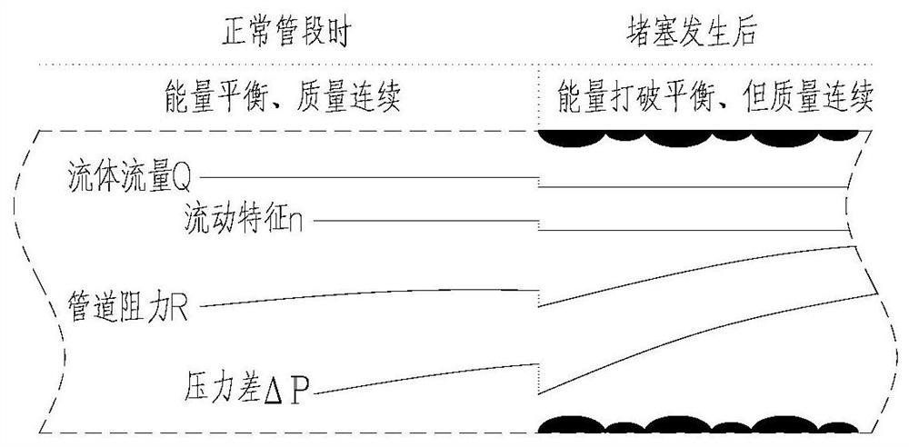
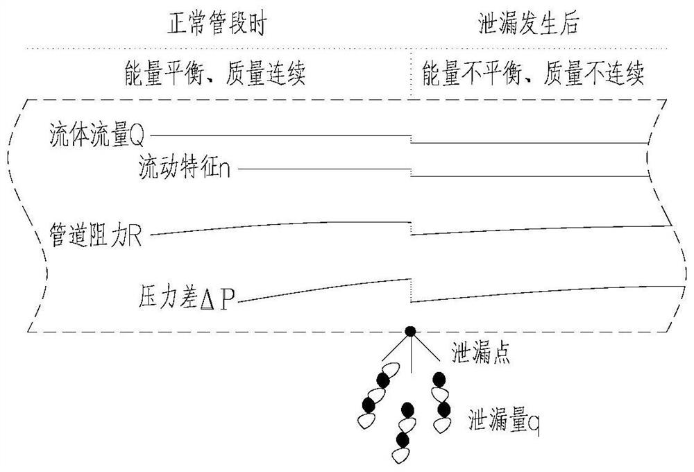
The invention provides a fault detection method and system for a fluid pipeline. The problems that a leakage and blockage detection method in the prior art cannot be applied to any pipeline and is nothigh in precision are solved. The method comprises the following steps of mapping the mutual constraint relation between the pipeline and fluid according to energy balance of the fluid in the pipeline, the flow of the fluid in the pipeline and the pressure difference value between the front end and the rear end of a pipeline section on the specified leakage and blockage detection pipe section; continuously obtaining a pipeline stroke resistance value R and a fluidity characteristic coefficient n through a machine self-learning mode as a normal reference sample; once the stroke resistance value R and the fluidity characteristic coefficient n change, determining that the pipeline is in an abnormal state; and capturing the time and the degree of quantitative change of the stroke resistance Rand the fluidity characteristic coefficient n, and identifying that the pipe section is in a quality change fault state of blockage or leakage. Through the machine self-learning mode, original parameters such as pipeline erection condition, section surface shape, clear viscous medium type and fast and slow flow speed do not need to be observed, and the application range is wide.

Description

technical field [0001] The invention relates to the technical field of measurement and control, in particular to a method and system for detecting a fault of a fluid pipeline. Background technique [0002] Liquid and gaseous media travel through the pipeline for a long time, and will accumulate sediment on the wall of the pipeline. These dirt will cause the flow resistance to gradually increase during the subsequent transmission process, and will also cause electrochemical corrosion of the pipeline material. Corrosion damage, accelerating pipe perforation leakage. [0003] Due to various erosion effects, unpredictable external force damage and other factors, most of the initial leakage has its own unique concealment, which is not very intuitive and obvious, especially the trace leakage is difficult to find. [0004] Once a continuous leakage accident occurs, it will not only interfere with normal production, cause economic losses, but also cause major safety hazards, and th...

Claims


Application Information

Patent Timeline
Patent Type & Authority Applications(China)
IPC IPC(8): F17D5/02F17D5/00
CPCF17D5/02F17D5/00
Inventor 胡狄辛于目奎张伟罗显科
Owner CISDI INFORMATION TECH CO LTD
Learn More