Method of determining cavitation threshold of liquid metal

A liquid metal and cavitation threshold technology, applied in design optimization/simulation, color TV parts, TV system parts, etc., can solve problems such as the inability to determine the liquid metal cavitation threshold

Active Publication Date: 2020-10-30
HARBIN INST OF TECH
View PDF8 Cites 0 Cited by
  • Summary
  • Abstract
  • Description
  • Claims
  • Application Information

AI Technical Summary

Problems solved by technology

[0004] The present invention solves the technical problem that the cavitation threshold of liquid metal can

Method used


Image

  • Method of determining cavitation threshold of liquid metal
  • Method of determining cavitation threshold of liquid metal
  • Method of determining cavitation threshold of liquid metal

Examples


specific Embodiment approach 1

[0033] Specific Embodiment 1: In this embodiment, a method for determining the cavitation threshold of liquid metal is carried out according to the following steps:

[0034] 1. Put the droplet of the liquid metal to be tested which is liquid at normal temperature on the transparent glass of the device for determining the cavitation threshold of the liquid metal;

[0035] Or place a non-liquid metal at normal temperature on the transparent glass of the liquid metal cavitation threshold device, and then heat the metal to a liquid state, which is the liquid metal to be tested;

[0036] 2. Turn on the ultrasound, and use a high-speed camera to shoot the spreading process of the liquid metal droplet to be tested;

[0037] 3. Select the photo taken in step 2, and record the width and shooting time of the liquid drop front without acoustic cavitation in the photo;

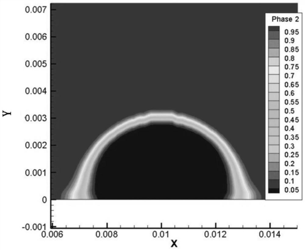
[0038] 4. Use finite element software to simulate the spreading process of the liquid metal to be tested;

[0039] 5....

specific Embodiment approach 2

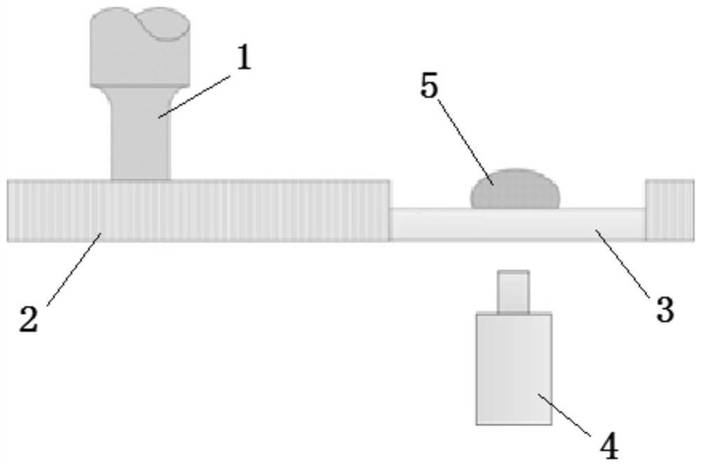
[0040] Embodiment 2: The difference between this embodiment and Embodiment 1 is that the device for determining the liquid metal cavitation threshold includes an ultrasonic tool head 1, a base material 2, a transparent glass 3 and a high-speed camera 4, wherein the transparent glass 3 replaces Part of the base material 2, and the transparent glass 3 is closely attached to the base material 2, the ultrasonic tool head 1 is closely attached to the upper surface of the base material 2, the liquid metal 5 to be tested is placed on the transparent glass 3, and the high-speed camera 4 is located on the transparent glass 3, the lens of the high-speed camera 4 is set directly below the liquid metal 5 to be tested, and faces the liquid metal 5 to be tested. Others are the same as in the first embodiment.

specific Embodiment approach 3

[0041] Embodiment 3: This embodiment is different from Embodiment 1 or Embodiment 2 in that: the base material is pure aluminum. Others are the same as in the first or second embodiment.


PUM


Abstract

The invention discloses a method for determining a cavitation threshold value of liquid metal, and relates to the field of acoustic cavitation of the liquid metal. The method aims to solve the technical problem that the cavitation threshold value of the liquid metal cannot be determined at present. The method comprises the following steps: shooting cavitation characteristics of a parent metal/liquid metal interface in the liquid metal ultrasonic-assisted spreading process by using high-speed photography; after cavitation shooting, measuring the area, where cavitation cannot happen, of the spreading front edge of the liquid drop; simulating the spreading process of the liquid drop through a finite element simulation method, and extracting the sound pressure of the edge of the area where cavitation cannot happen, namely a cavitation threshold value. The method is simple to operate, low in cost and accurate in result; and the method is not limited by liquid metal components and has a wideapplication range. The method is used for determining the cavitation threshold of the liquid metal.

Description

technical field [0001] The invention relates to the field of acoustic cavitation of liquid metals. Background technique [0002] Acoustic cavitation of liquid is widely used in processes such as ultrasonic cleaning, ultrasonic extraction, ultrasonic catalysis, ultrasonic lithotripsy and ultrasonic melt treatment. It can not only accelerate the speed of chemical reactions, improve extraction and catalytic efficiency, but also refine Melt structure, improve the efficiency of ultrasonic welding, etc. Acoustic cavitation refers to a series of processes of nucleation, growth, oscillation, and final collapse of tiny bubbles in a liquid under the action of ultrasonic waves. The collapse of cavitation bubbles will produce a series of local, extreme, and instantaneous phenomena, such as high temperatures of thousands of degrees, pressures of hundreds of megapascals, and liquid velocities of hundreds of meters per second. Most of the industrial applications of ultrasonic cavitation ...

Claims


Application Information

Patent Timeline
IPC IPC(8): G06F30/23H04N5/232G06F113/08
CPCG06F30/23G06F2113/08H04N23/80
Inventor 李政玮许志武闫久春
Owner HARBIN INST OF TECH
Why Eureka
Try Eureka