
Steel bar straightening, bending and shearing continuous production device

A technology for production device and steel bar, applied in the field of steel bar straightening, bending and shearing continuous production device, it can solve the problems of uneven stress on fasteners, affecting shear quality, looseness, etc. High bending efficiency

Active Publication Date: 2020-11-03
CHINA METALLURGICAL CONSTR ENG GRP
View PDF9 Cites 4 Cited by
  • Summary
  • Abstract
  • Description
  • Claims
  • Application Information

AI Technical Summary

Problems solved by technology

However, when the device bends the steel bar, after the steel bar is sent from the straightening mechanism between the movable bending axis and the fixed bending axis, in the process of bending, the bending part of the steel bar is far away from the straightening and clamping part, so that it is easy to bend when bending. In the event of arching or improper bending, it is necessary to stop the machine to adjust the steel bar, or directly scrap the steel bar, which will affect the next continuous operation of the bending mechanism
Simultaneously, the movable cutter of the shearing mechanism of this device is installed on the side end of the shearing arm, and is obliquely sheared in the shearing process, and the bottom and the side end of the movable cutter all do not have support, only by fastening After long-term use, it is easy to cause uneven force on the fastener, loosening or displacement, which will affect the cutting quality, and it will be scrapped before the cutting edge is completely worn.

Method used


Image

  • Steel bar straightening, bending and shearing continuous production device
  • Steel bar straightening, bending and shearing continuous production device
  • Steel bar straightening, bending and shearing continuous production device

Examples


Embodiment

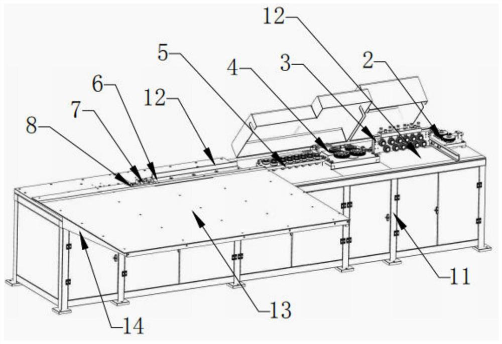
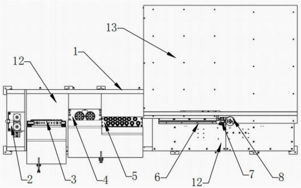
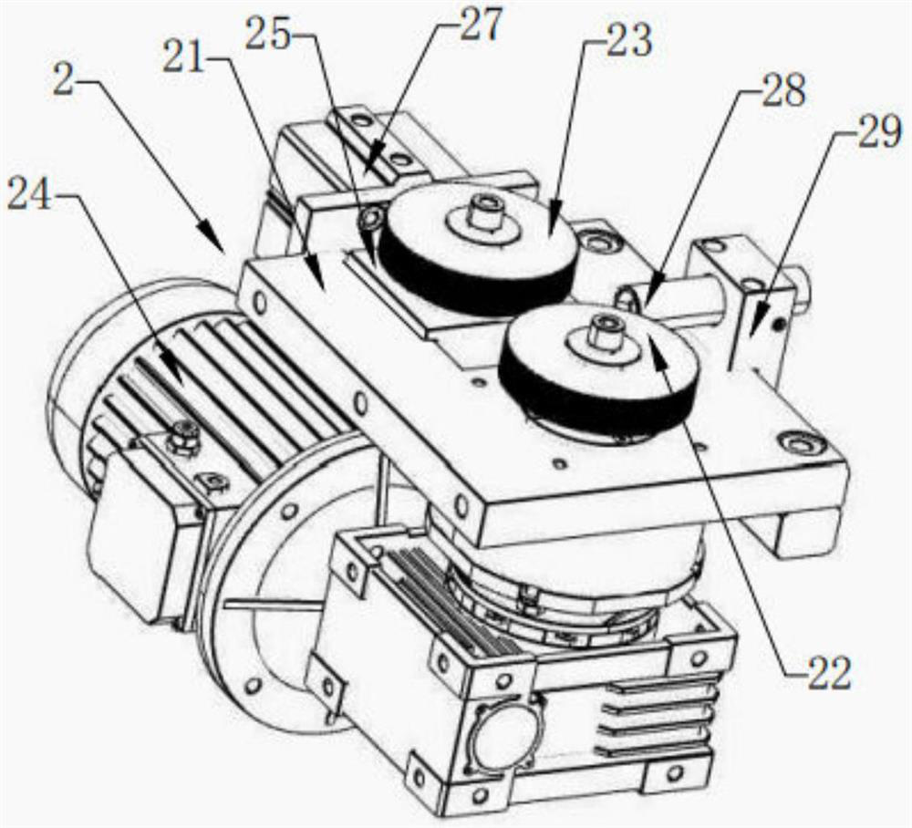
[0036] As shown in the figure, the steel bar straightening, bending and shearing continuous production device provided by this embodiment, the frame 1, on the frame 1, steel bar straightening is installed sequentially from the feed end to the discharge end of the frame 1. Straightening mechanism, steel bar shearing mechanism 7 and steel bar bending mechanism 8, described steel bar straightening mechanism comprises steel bar vertical straightening module 3 and steel bar horizontal straightening module 5, in steel bar vertical straightening module and steel bar horizontal straightening module 5 There is a steel bar feeding mechanism 4 between them; before the steel bar straightening mechanism, there is also a steel bar traction mechanism 2 that can automatically send the whole bundle of steel bars to the horizontal straightening mechanism, and between the steel bar shearing mechanism 7 and the steel bar straightening mechanism There is also a steel bar coarse positioning mechanis...


PUM


Abstract

The invention discloses a steel bar straightening, bending and shearing continuous production device which comprises a rack, and a steel bar straightening mechanism, a steel bar shearing mechanism anda steel bar bending mechanism are sequentially installed from the feeding end to the discharging end of the rack. A steel bar traction mechanism is further arranged in front of the steel bar straightening mechanism, and a steel bar coarse positioning mechanism is further arranged between the steel bar shearing mechanism and the steel bar straightening mechanism. A to-be-machined steel bar is fedinto the steel bar straightening mechanism, the steel bar coarse positioning mechanism and the steel bar shearing mechanism through the traction mechanism, then enters a steel bar positioning piece ofthe steel bar bending mechanism, then rotates back and forth multiple times through a movable bending rod, and is bent after the to-be-machined steel bar rotates back and forth four times through themovable bending rod in the rotating process, a stirrup is formed, the stirrup and the to-be-machined steel bar are cut off through upward swinging of a movable cutter of a steel bar swinging and shearing assembly, and bending and shearing machining are repeated after machining of one stirrup is completed.

Description

technical field [0001] The invention relates to a steel bar processing device, in particular to a steel bar straightening, bending and shearing continuous production device. Background technique [0002] Existing automatic hoop bending machine comprises: feeding mechanism, straightening mechanism, bending mechanism and shearing mechanism. At present, the Chinese patent application number 2004200293972 discloses a continuous production device for steel bar straightening, shearing and bending, which realizes continuous production and processing of steel bar conveying, straightening, shearing and bending through automatic control means, greatly It greatly saves the cost of steel bar bending hoops, reduces the labor intensity of the operator, and the quality of the hoops after processing is good. However, when the device bends the steel bar, after the steel bar is sent from the straightening mechanism between the movable bending axis and the fixed bending axis, in the process o...

Claims


Application Information

Patent Timeline
IPC IPC(8): B21F1/02B21F11/00B21F1/00B21F23/00
CPCB21F1/026B21F11/00B21F1/00B21F23/00
Inventor 田达菲唐德军陈涛陈刚李智能
Owner CHINA METALLURGICAL CONSTR ENG GRP
Learn More