Progressive die stamping device
A punching device and punching machine technology, applied in the field of continuous die punching device, can solve the problem of uneven punching incision, achieve the effect of uniform incision and prevent offset
- Summary
- Abstract
- Description
- Claims
- Application Information
AI Technical Summary
Problems solved by technology
Method used
Image
Examples
Embodiment 1
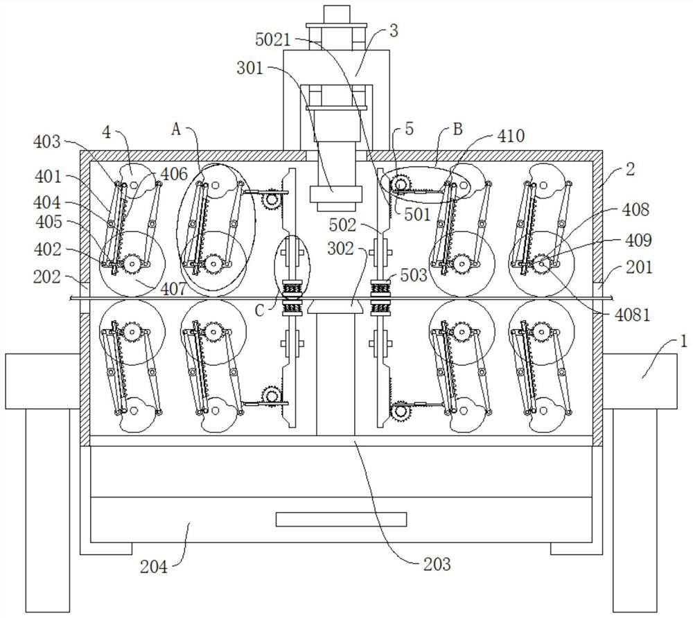
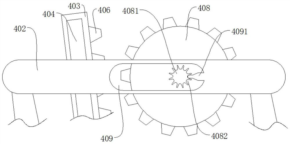
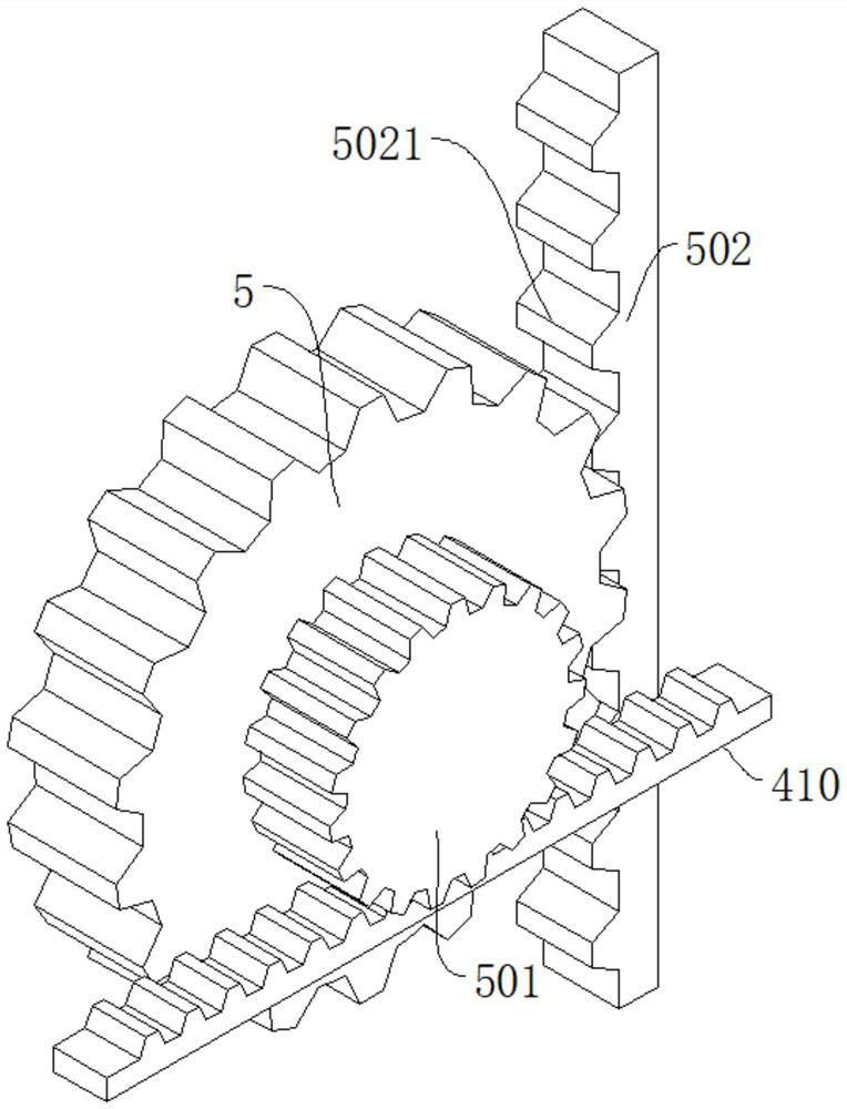
[0028] refer to Figure 1-6 , a continuous die stamping device, comprising a base 1 and a box body 2, the box body 2 is fixedly connected to the base 1, the top of the box body 2 is fixedly connected to a punching machine body 3, the bottom of the punching machine body 3 is provided with a movable mold 301, and the box The bottom of the body 2 is connected with a static mold 302 corresponding to the movable mold 301, the side wall of the box body 2 is provided with a feed port 202 and a first discharge port 201, and the bottom of the box body 2 is provided with a second discharge port 203. Including the conveying wheel 407, which is two in multiple groups, and the two conveying wheels 407 in each group fit together to place the workpiece, and the workpiece is moved by the conveying wheel 407, and the conveying wheel 407 stops, and the workpiece stops; the pressing part , located on both sides of the static mold 302, used to press and hold the workpiece; the driving part; where...
Embodiment 2
[0030] refer to Figure 1-6 , a continuous die stamping device, comprising a base 1 and a box body 2, the box body 2 is fixedly connected to the base 1, the top of the box body 2 is fixedly connected to a punching machine body 3, the bottom of the punching machine body 3 is provided with a movable mold 301, and the box The bottom of the body 2 is connected with a static mold 302 corresponding to the movable mold 301, the side wall of the box body 2 is provided with a feed port 202 and a first discharge port 201, and the bottom of the box body 2 is provided with a second discharge port 203. Including the conveying wheel 407, which is two in multiple groups, and the two conveying wheels 407 in each group fit together to place the workpiece, and the workpiece is moved by the conveying wheel 407, and the conveying wheel 407 stops, and the workpiece stops; the pressing part , located on both sides of the static mold 302, used to press and hold the workpiece; the driving part; where...
Embodiment 3
[0036] refer to Figure 1-6 , a continuous die stamping device, comprising a base 1 and a box body 2, the box body 2 is fixedly connected to the base 1, the top of the box body 2 is fixedly connected to a punching machine body 3, the bottom of the punching machine body 3 is provided with a movable mold 301, and the box The bottom of the body 2 is connected with a static mold 302 corresponding to the movable mold 301, the side wall of the box body 2 is provided with a feed port 202 and a first discharge port 201, and the bottom of the box body 2 is provided with a second discharge port 203. Including the conveying wheel 407, which is two in multiple groups, and the two conveying wheels 407 in each group fit together to place the workpiece, and the workpiece is moved by the conveying wheel 407, and the conveying wheel 407 stops, and the workpiece stops; the pressing part , located on both sides of the static mold 302, used to press and hold the workpiece; the driving part; where...
PUM
 Abstract
Description
Claims
Application Information
 - R&D
- Intellectual Property
- Life Sciences
- Materials
- Tech Scout
- Unparalleled Data Quality
- Higher Quality Content
- 60% Fewer Hallucinations
Browse by: Latest US Patents, China's latest patents, Technical Efficacy Thesaurus, Application Domain, Technology Topic, Popular Technical Reports.
© 2025 PatSnap. All rights reserved.Legal|Privacy policy|Modern Slavery Act Transparency Statement|Sitemap|About US| Contact US: help@patsnap.com


