
Pipeline cutting device with rotary cutting function for constructional engineering

A technology for construction engineering and pipe cutting, which is applied in the direction of pipe shearing devices, shearing devices, and attachments of shearing machines. Potential safety hazard, life extension effect

Inactive Publication Date: 2022-04-12
吴迪
View PDF4 Cites 0 Cited by
  • Summary
  • Abstract
  • Description
  • Claims
  • Application Information

AI Technical Summary

Problems solved by technology

The prior art publication No. CN213796713U provides a pipe cutting device for construction engineering. The device clamps and fixes the outer wall of the pipe through two clamping plates. It is still easy to cut when only one end of the pipe is clamped. When the two ends of the pipe are clamped separately, the clamping structure is relatively complicated, which makes the device bulky. Secondly, the cutting blade is directly exposed after use or when it is not in use, posing a safety hazard. And make the cutting blade easy to rust and affect the service life
The prior art publication numbers CN212121866U and CN212070569U have the same problem. Although the cutting blade is set inside the device in CN207952768U, the cutting blade is always inside the device. When the cutting blade needs to be replaced, the whole device needs to be disassembled. Make blade replacement very troublesome

Method used


Image

  • Pipeline cutting device with rotary cutting function for constructional engineering
  • Pipeline cutting device with rotary cutting function for constructional engineering
  • Pipeline cutting device with rotary cutting function for constructional engineering

Examples


Embodiment Construction

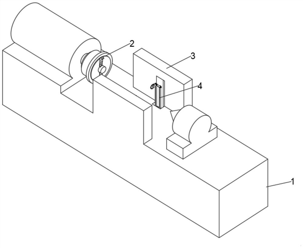
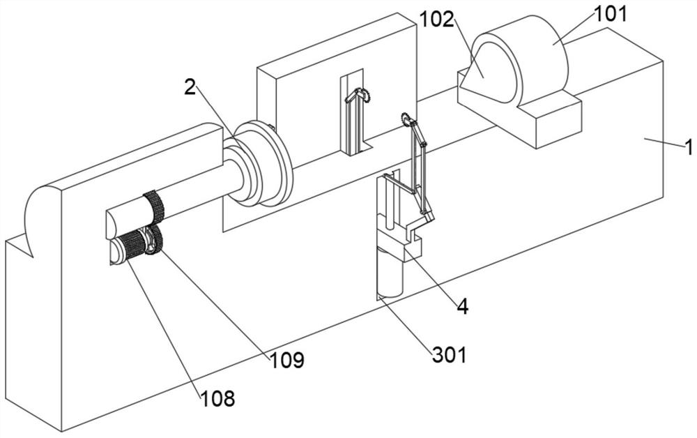
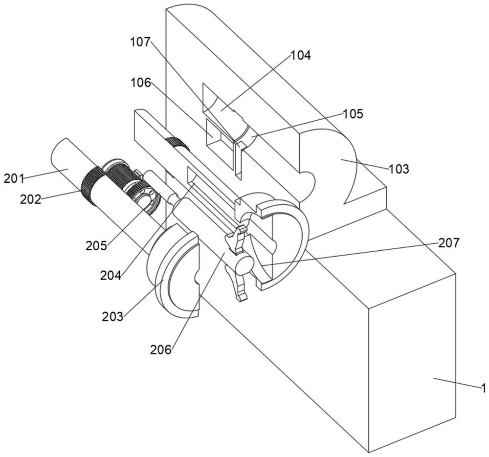
[0027] see Figure 1-5 , the present invention provides a specific embodiment:

[0028] A pipe cutting device for construction engineering with a rotary cutting function, comprising a workbench 1, such as figure 2 and image 3 As shown, a centering block 101 is slidingly arranged on the outside of the surface of the workbench 1, and a conical centering block 102 is provided on one side of the centering block 101; a cutting processing block 103 is provided on the inside of the surface of the workbench 1, and a Circular groove 104, the inner wall of circular groove 104 is provided with annular groove 105, and circular groove 104 interior is provided with limit rotation rotary cutting mechanism 2; One side of cutting processing block 103 interior offers organic chamber 106, and machine chamber 106 outside offers circular groove 106. Slot 107, motor 108 is provided inside the machine cavity 106, the output end of the motor 108 extends through the inner wall of the machine cavit...


PUM


Abstract

The invention discloses a constructional engineering pipeline cutting device with a rotary cutting function, and belongs to the technical field of constructional engineering pipeline cutting devices.The constructional engineering pipeline cutting device comprises a workbench, a centering block is slidably arranged on one side of the surface of the workbench, a conical centering block is arranged on one side of the centering block, and a cutting treatment block is arranged on the inner side of the surface of the workbench; and a limiting autorotation rotary cutting mechanism is rotationally arranged in the cutting treatment block, and the first fixing block completes rotation opening and closing of the first fixing block by means of telescopic movement of the fixing telescopic column, so that the inner wall of the pipeline is fixed and loosened by the first fixing block. Through the arrangement of the limiting autorotation rotary cutting mechanism, after the pipeline is fixed, cutting can be conducted through autorotation of the pipeline, at the moment, the pipeline is a power part, a cutter is a static part, the circumferential outer wall of the pipeline can be evenly and rotationally cut, therefore, notches are even, and later use of the pipeline is guaranteed.

Description

technical field [0001] The invention relates to the technical field of pipe cutting devices for construction engineering, and more specifically, relates to a pipe cutting device for construction engineering with a rotary cutting function. Background technique [0002] Pipes need to be cut during construction. The prior art publication No. CN213796713U provides a pipeline cutting device for construction engineering. The device clamps and fixes the outer wall of the pipeline through two clamping plates. It is still easy to cut when only one end of the pipeline is clamped. When the two ends of the pipe are clamped separately, the clamping structure is relatively complicated, which makes the device bulky. Secondly, the cutting blade is directly exposed after use or when it is not in use, posing a safety hazard. And make the cutting blade easy to rust and affect the service life. The prior art publication numbers CN212121866U and CN212070569U have the same problem. Although the...

Claims


Application Information

Patent Timeline
Patent Type & Authority Applications(China)
IPC IPC(8): B23D21/04B23D33/02B23Q3/12B23Q5/28
Inventor 高慧茹
Owner 吴迪
Learn More