
Automobile die grinding and polishing assembly

A technology for automotive molds and components, applied in grinding/polishing equipment, grinding/polishing safety devices, grinding workpiece supports, etc., can solve problems affecting the production of accessories, inconvenient removal of burrs, economic losses, etc., to ensure processing Production, avoiding economic loss, ensuring the effect of grinding effect

Inactive Publication Date: 2020-12-11
孙涛
View PDF13 Cites 0 Cited by
  • Summary
  • Abstract
  • Description
  • Claims
  • Application Information

AI Technical Summary

Problems solved by technology

[0004] The purpose of the present invention is to solve the shortcomings of the existing mold burrs that are inconvenient to remove, affect the production of later accessories, and cause unnecessary economic losses, and propose a grinding and polishing assembly for automobile molds

Method used


Image

  • Automobile die grinding and polishing assembly
  • Automobile die grinding and polishing assembly
  • Automobile die grinding and polishing assembly

Examples


Embodiment 1

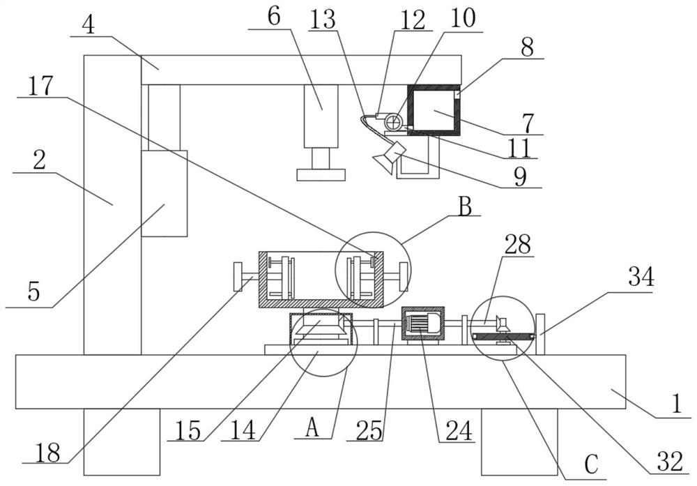
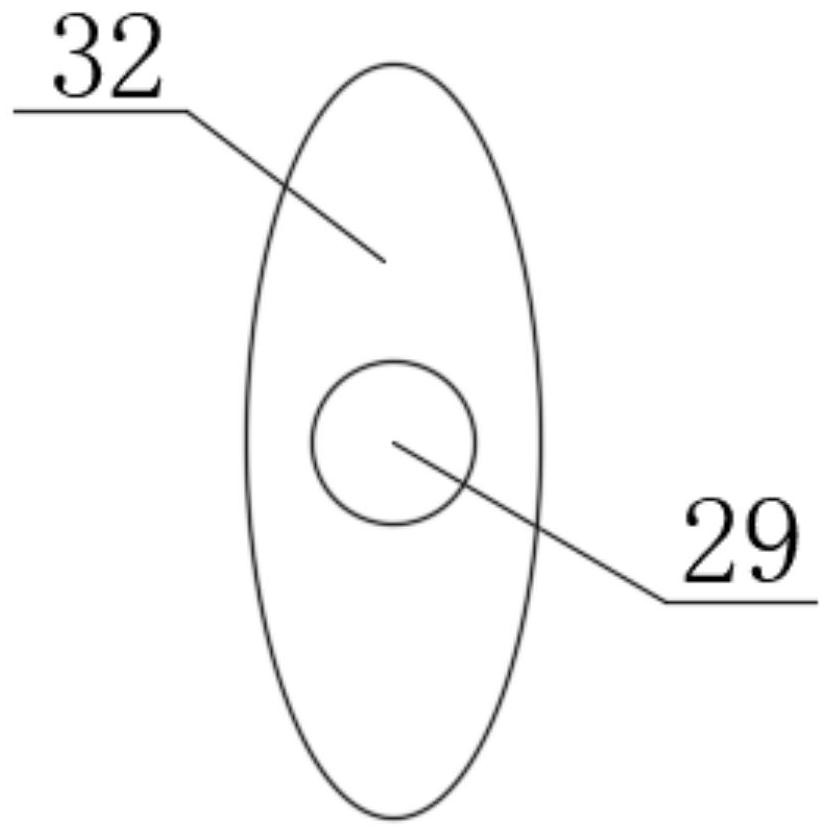
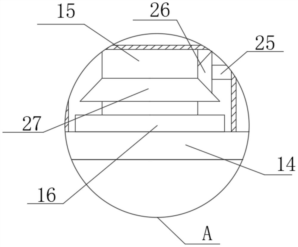
[0026] refer to Figure 1-5 , an automobile mold grinding and polishing assembly, comprising a base 1, a first mounting plate 2 is fixedly mounted on the top of the base 1, a second mounting plate 4 is slidably mounted on one side of the first mounting plate 2, and the bottom of the second mounting plate 4 A grinding and polishing machine 6 is fixedly installed, an electric push rod 5 is fixedly installed on one side of the first mounting plate 2, the output shaft of the electric push rod 5 is fixedly connected with the second mounting plate 4, and the bottom of the second mounting plate 4 is fixedly installed with The material receiving box 7 is provided with a discharge port 8 on the material receiving box 7, and a pump machine 10 is fixedly installed on one side of the material receiving box 7, and the pump machine 10 is fixedly installed due to the suction pipe 11 and the discharge pipe 12. The bottom of the box 7 is fixed with a powder suction head 9, and one end of the h...

Embodiment 2

[0035] refer to Figure 1-5, an automobile mold grinding and polishing assembly, comprising a base 1, the top of the base 1 is fixedly installed with a first mounting plate 2 by welding, one side of the first mounting plate 2 is slidably mounted with a second mounting plate 4, and the second mounting plate 4 Grinding and polishing machine 6 is fixedly installed on the bottom by welding, and an electric push rod 5 is fixedly installed on one side of the first mounting plate 2 by screws. The output shaft of the electric push rod 5 is fixedly connected with the second mounting plate 4, and the second mounting plate The bottom of 4 is fixedly installed with receiving box 7 by welding, and is provided with discharge opening 8 on the receiving box 7, and the pump machine 10 is fixedly installed on one side of receiving box 7 by screw, is fixedly installed by welding on the pump machine 10 because The suction pipe 11 and the discharge pipe 12, the bottom of the material receiving box...


PUM


Abstract

The invention belongs to the technical field of grinding and polishing devices, particularly relates to an automobile die grinding and polishing assembly, and aims to solve the problems that burrs ofan existing die are inconvenient to remove, later accessory manufacturing is affected, and unnecessary economic losses are caused. According to the scheme, the automobile die grinding and polishing assembly comprises a base; a first mounting plate is fixedly mounted at the top of the base; a second mounting plate is slidably mounted on one side of the first mounting plate; a grinding and polishingmachine is fixedly mounted at the bottom of the second mounting plate; an electric push rod is fixedly mounted on one side of the first mounting plate; an output shaft of the electric push rod is fixedly connected with the second mounting plate; a collecting box is fixedly mounted at the bottom of the second mounting plate and provided with a discharging port; and a pump machine is fixedly mounted on one side of the collecting box. The automobile die grinding and polishing assembly has the advantages that convenience is brought to use, dies can be effectively and evenly ground and polished, the machining quality of accessories is guaranteed, later use is guaranteed, and economic losses are avoided.

Description

technical field [0001] The invention relates to the technical field of grinding and polishing devices, in particular to an automotive mold grinding and polishing assembly. Background technique [0002] The most important part of the automobile mold is the cover mold. This type of mold is mainly a cold stamping mold. In a broad sense, "automotive mold" is the general term for molds that manufacture all parts on automobiles. For example, stamping molds, injection molds, forging molds, casting wax patterns, glass molds, etc. [0003] However, the existing molds often have some burrs during production. If the burrs are not removed, the production quality of the auto parts will often be affected in the later production of auto parts, resulting in inconvenient use and unqualified parts. If it cannot be put into use, it will also cause certain economic losses. Contents of the invention [0004] The purpose of the present invention is to solve the disadvantages of inconvenient...

Claims


Application Information

Patent Timeline
Patent Type & Authority Applications(China)
IPC IPC(8): B24B19/20B24B27/00B24B41/06B24B55/06B24B41/02B24B47/04
CPCB24B19/20B24B27/0046B24B41/02B24B41/06B24B47/04B24B55/06
Inventor 孙涛
Owner 孙涛
Learn More