Casting iron pan polishing machine

A technology of polishing machine and cast iron pot, applied in grinding/polishing equipment, grinding workpiece support, grinding machine, etc., can solve the problems of cumbersome process, dust pollution, low polishing efficiency, etc., to improve efficiency, protect physical health and life Safe and good polishing effect

Active Publication Date: 2017-01-11
刘顺亮
View PDF8 Cites 2 Cited by
  • Summary
  • Abstract
  • Description
  • Claims
  • Application Information

AI Technical Summary

Problems solved by technology

[0003] The purpose of the present invention is to overcome the problems of low polishing efficiency, cumbersome process and serious dust pollution of the current iron pan polishing device, and provide a cast iron pan polishing machine, which can automatically move the position, and is convenient for polishing the pan blank. Good quality and able to remove dust effectively

Method used


Image

  • Casting iron pan polishing machine
  • Casting iron pan polishing machine
  • Casting iron pan polishing machine

Examples


Embodiment 1

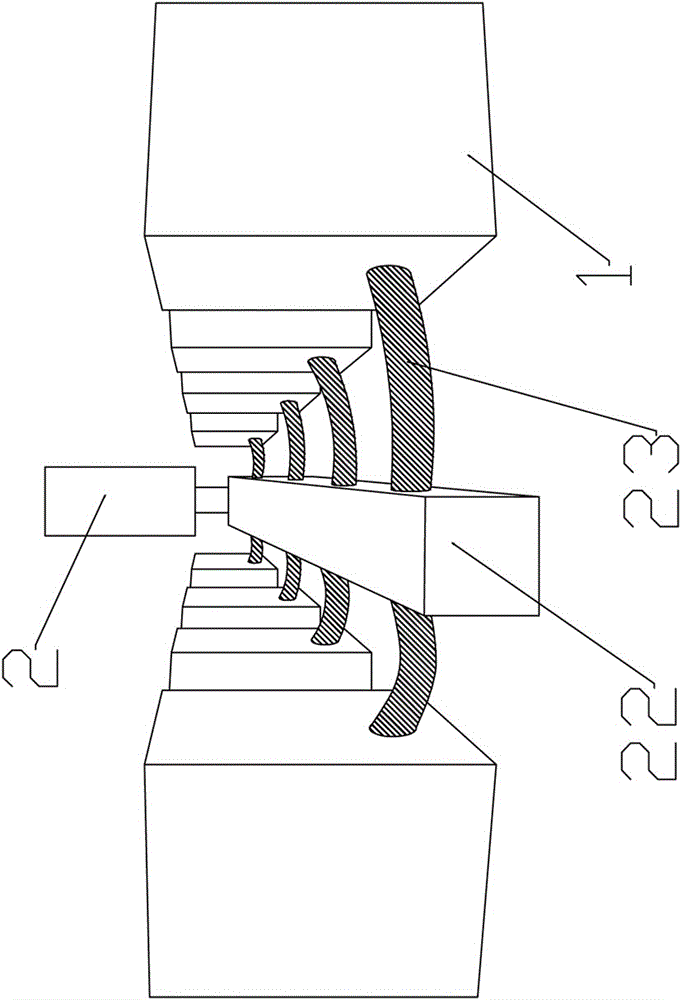
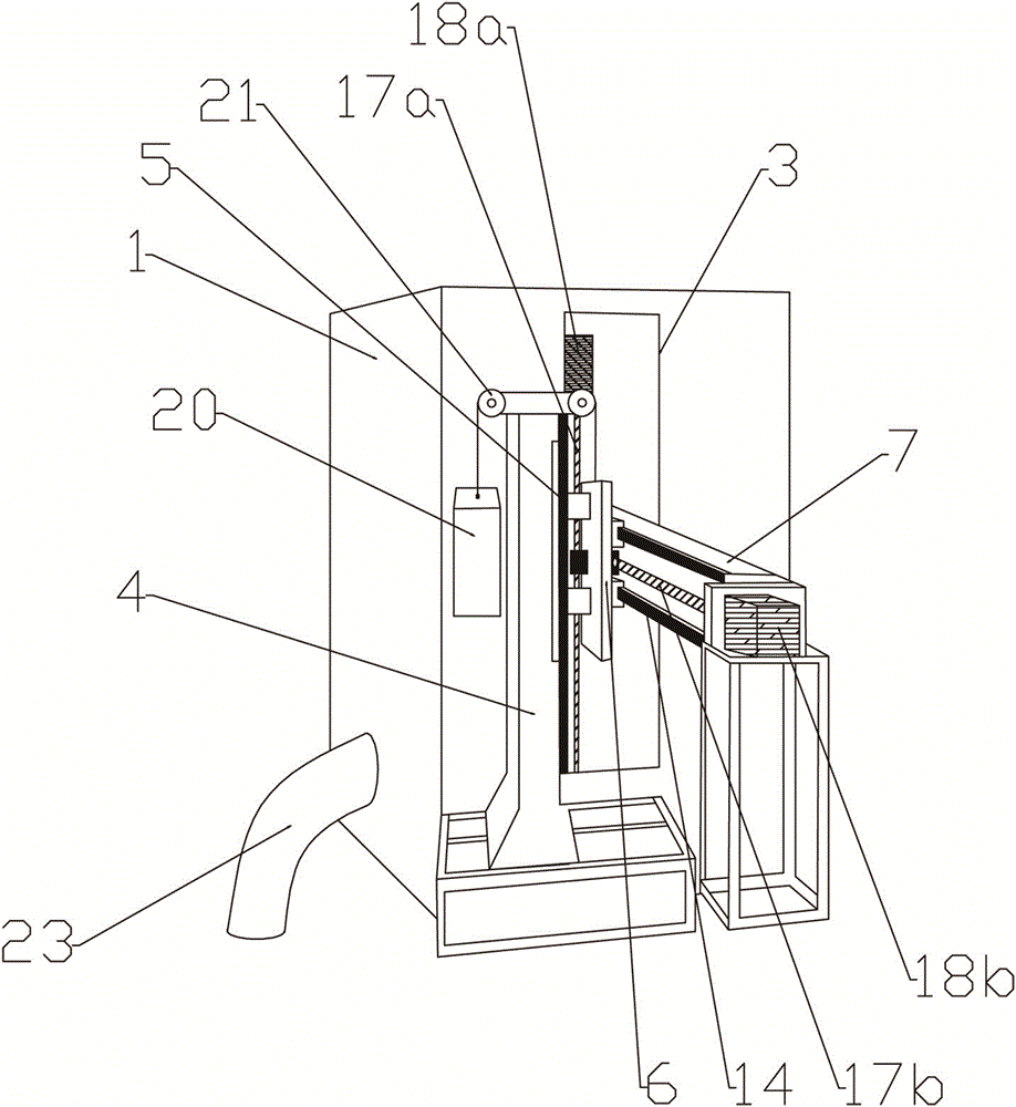
[0037] Embodiment 1: a kind of cast iron pan polishing machine, as Figure 1~17 As shown, it includes a chassis 1 and a dust removal device 2 connected to the chassis. The side wall of the chassis is vertically provided with an excavation frame 3, and a transmission device is arranged at the excavation frame. A machine head device is arranged on the top of the interior of the chassis, and a workpiece fixing device is arranged on the bottom. ;

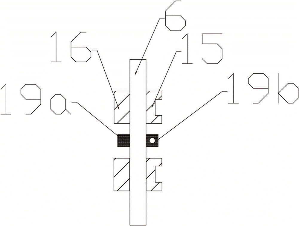
[0038]The transmission device includes a vertical arm 4 arranged outside the chassis, on which a vertical guide rail 5 is installed, on the vertical guide rail is provided with a fixed seat 6 that moves up and down along the direction of the guide rail, and on the fixed seat is provided with a front and rear horizontally movable Cross arm 7, horizontal guide rail 14 is provided on the cross arm, the horizontal chute 15 that cooperates with horizontal guide rail is installed on one side of fixed base 6, the vertical chute 16 that coopera...

Embodiment 2

[0043] Example 2: The cast iron pan polisher of the present example will be described centering on the differences from the cast iron pan polisher related to Example 1.

[0044] like Figure 8~10 As shown, the abrasive belt support wheel mounting device is fixedly installed on the two support wheel mounting plates 10, which includes a support wheel fixed seat plate 24 fixedly installed on the outside of the support wheel mounting plate, and a guide hole is arranged on the support wheel fixed seat plate. The guide rod 25 is inserted in the guide hole, the guide rod is provided with a positioning nut 26, the positioning nut is located above the support wheel fixed seat plate, the lower end of the guide rod is fixedly connected with the support wheel mounting seat 27, and the abrasive belt support wheel 12 is installed through the pin shaft On the support wheel mounting seat, the guide rod 25 is also provided with a compression spring 28, and the compression spring is located bet...


PUM


Abstract

The invention relates to a casting iron pan polishing machine, which comprises a case and dust removing equipment connected with the case. A digging and storing frame and a transmission device are arranged on the side wall of the case; a machine head device is arranged on the upper part in the case; a workpiece fixing device is arranged on the lower part in the case; the transmission device comprises a vertical guide rail arranged outside the case; a fixed seat vertically moving along a direction of the guide rail is arranged on the vertical guide rail; a cross arm capable of horizontally moving front and back is arranged on the fixed seat, and penetrates through the digging and storing frame so as to be connected with the machine head device; the machine head device comprises a fixed seat plate and a double-end motor; abrasive belt driving wheels are arranged on two sides of the double-end motor; two abrasive belt supporting wheels are arranged right below the two abrasive belt driving wheels; a rough polishing abrasive belt and a fine polishing abrasive belt are arranged on the abrasive belt driving wheels and the abrasive belt supporting wheels on two sides in a sleeving way; the workpiece fixing device comprises a supporting plate arranged on the lower part of the case; a base is arranged on the supporting plate; and a transmission mechanism is arranged between the case and the supporting plate. The casting iron pan polishing machine is high in polishing efficiency and good in quality.

Description

technical field [0001] The invention relates to an iron pan polishing device, in particular to a cast iron pan polishing machine. Background technique [0002] At present, the polishing of iron pots is performed by manual production, which has low polishing efficiency, high damage rate of iron pots, and the polishing quality cannot be guaranteed; although there are already automatic polishing machines, the existing polishing machines do not work continuously, because both the inside and outside of the pot blank need to be polished, and The inside and outside must be rough polished first, and then finely polished. Due to the limitations of the existing polishing machine’s own structural design, there is often only one head. During the process of running over the pot blank, one polishing machine can only complete one polishing job. , but cannot achieve continuous polishing. After completing a process, it is often necessary to transfer the pot blank to the next process, and the...

Claims


Application Information

Patent Timeline
IPC IPC(8): B24B21/00B24B21/02B24B21/20B24B41/06
CPCB24B21/006B24B21/02B24B21/20B24B41/061
Inventor 刘顺亮
Owner 刘顺亮
Why Eureka
Try Eureka