
A storage device for electronic components

A technology for electronic components and storage devices, which is applied to internal accessories, drawer-type containers, etc., can solve problems such as inconvenient access, and achieve the effects of convenient access, saving picking and placing time, and simplifying the picking and placing process.

Active Publication Date: 2022-03-11
NANJING COLLEGE OF INFORMATION TECH
View PDF11 Cites 0 Cited by
  • Summary
  • Abstract
  • Description
  • Claims
  • Application Information

AI Technical Summary

Problems solved by technology

[0004] Purpose of the invention: The purpose of the present invention is to provide a storage device for electronic components, which solves the problem that the existing storage devices need to open the corresponding locks one by one when the electronic components need to be taken and placed, resulting in inconvenient access.

Method used


Image

  • A storage device for electronic components
  • A storage device for electronic components
  • A storage device for electronic components

Examples


Embodiment 1

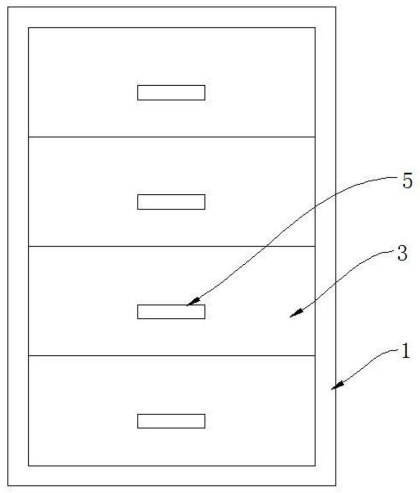
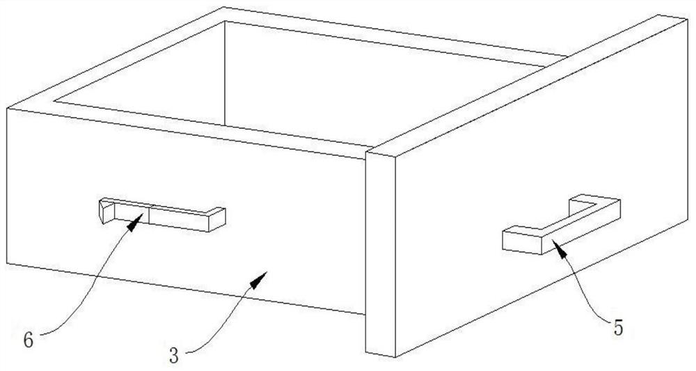
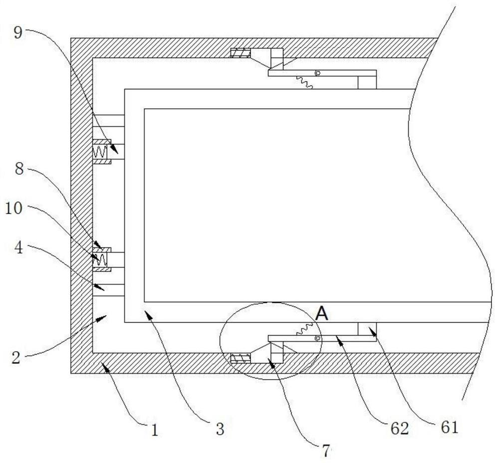
[0021] Such as Figure 1 to Figure 4 As shown, the present invention is a storage device for electronic components, including a cabinet body 1, the interior of the cabinet body 1 is fixedly connected with multiple sets of horizontal and spaced partitions 2 from top to bottom, each group of partitions 2 All are slidably connected with a drawer 3, which is specifically: a guide rail 4 is fixedly installed on the partition 2, and a moving block that is slidingly matched with the guide rail 4 is provided on the guide rail 4, and the moving block is fixedly connected with the bottom of the drawer 3, This allows the storage drawer 3 to slide on the partition 2;

[0022] The front faces of each group of drawers 3 are fixedly equipped with handles 5, and the left and right side walls of each group of drawers 3 are fixedly equipped with limiting components 6, and the inner wall of the cabinet body 1 is provided with multiple sets of limiting components 6. The gear assembly 7 correspon...

Embodiment 2

[0029] This embodiment is basically the same as Embodiment 1, and the distinguishing features are:

[0030] The inner wall of the cabinet body 1 is also fixedly provided with a guide cylinder 8, and the guide cylinder 8 is inserted with a top strut 9. The top strut 9 is fixedly connected with the side wall of the storage drawer 3, and the top strut 9 is far away from the storage drawer 3. A third elastic body 10 is provided between one end of the upper end and the guide cylinder 8, and the third elastic body 10 is a spring. The drawer 3 can act on the top support rod 9, so that the top support rod 9 moves inside the guide cylinder 8, and then drives the third elastic body 10 to compress or elongate. The third elastic body 10 provides buffer and protection for the storage drawer 3, Rigid contact between the storage drawer 3 and the inner wall of the cabinet body 1 can be avoided, and the electronic components inside the storage drawer 3 can be avoided from shaking, causing them...


PUM


Abstract

The invention discloses a storage device for electronic components, which comprises a cabinet body. The interior of the cabinet body is fixedly connected with multiple sets of horizontal partitions arranged at intervals from top to bottom, and each group of partitions is slidably connected. There are storage drawers, and the left and right side walls of each set of storage drawers are fixedly equipped with limiting components, and the inner wall of the cabinet is provided with multiple groups of gear components corresponding to the positions of the limiting components. The present invention can realize the locking of the storage drawer inside the cabinet through the setting of the non-return block and the limit block, so as to prevent the storage drawer from being pulled out for no reason; at the same time, through the setting of the slider, the rapid withdrawal of the storage drawer can also be realized , to place and take electronic components, which has the advantages of convenient access and good storage effect. Compared with the prior art, it greatly simplifies the process of picking and placing electronic components and saves picking and placing time.

Description

technical field [0001] The invention relates to the technical field of storage of electronic components, in particular to a storage device for electronic components. Background technique [0002] Electronic components are components of electronic components and small machines and instruments, which are often composed of several parts. [0003] At present, in order to realize the classified storage of electronic components, most of the electronic components of the same type are placed in the same drawer, and the drawer is slidably installed with the corresponding cabinet body, so that the drawer can slide into the inside of the cabinet body during storage. Protection, at the same time, in order to prevent the drawer from being opened at will, the drawer and the cabinet body are also connected by locks. In this way, when it is necessary to take and place electronic components, the corresponding locks need to be opened one by one, resulting in inconvenient access. Contents of...

Claims


Application Information

Patent Timeline
Patent Type & Authority Patents(China)
IPC IPC(8): B65D25/04B65D6/06B65D25/02
CPCB65D25/04B65D25/02
Inventor 袁小燕顾振飞鲍安平王书旺张志友李娟
Owner NANJING COLLEGE OF INFORMATION TECH
Learn More