Tool for CNC tool grinder

A tool grinding machine and tool technology, which is applied in the direction of grinding bed, manufacturing tools, grinding skateboards, etc., can solve the problems of damage and difficult cleaning, and achieve the effects of avoiding damage, facilitating grinding processing, and increasing processing strength

Active Publication Date: 2021-10-26
东莞市御钻数控科技有限公司
View PDF8 Cites 0 Cited by
  • Summary
  • Abstract
  • Description
  • Claims
  • Application Information

AI Technical Summary

Problems solved by technology

[0003] At present, there is a cutting tool for CNC tool grinding machine. When the cutting tool is processed and repaired, the high-speed friction between the grinding machine tool and the processed tool will be smoothed by the surface of the processed tool. At this time, a large amount of waste chips will be generated. These waste chips Fly out along the direction of grinding tool rotation, in order to avoid the waste chips flying out and hurting the operator, the waste chips are usually separated by the baffle, but the waste chips after the separation fall down to the CNC tool under the action of gravity Difficult to clean inside the grinder

Method used


Image

  • Tool for CNC tool grinder
  • Tool for CNC tool grinder
  • Tool for CNC tool grinder

Examples


Embodiment 1

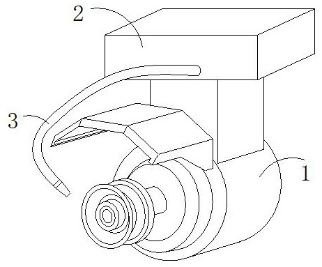
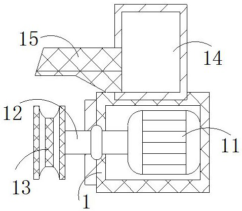
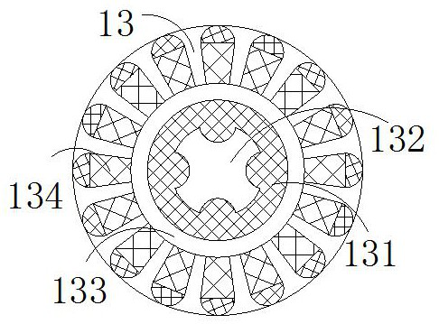
[0029] The invention provides a tool for CNC tool grinder, the structure of which includes a positioning box 1, a fixing block 2, and a cooling pipe 3, the bottom of the fixing block 2 is welded to the top of the positioning box 1, and one end of the cooling pipe 3 is embedded in a fixed On the front side of the block 2, the positioning box 1 includes a driving machine 11, a rotating shaft 12, a grinder tool 13, an isolation chamber 14, and a baffle plate 15, and the driving machine 11 is cooperatingly installed inside the positioning box 1, and the rotating shaft 12 runs through the positioning box 1. The left wall is connected to the driving machine 11. The grinder tool 13 is nested on the outer surface of the left end of the rotating shaft 12. The isolation cavity 14 is embedded in the upper interior of the positioning box 1. The right side of the baffle plate 15 is embedded in the isolation cavity. The left wall of 14 is located directly above the grinder cutter 13. The dia...

Embodiment 2

[0035]The invention provides a tool for CNC tool grinder, the structure of which includes a positioning box 1, a fixing block 2, and a cooling pipe 3, the bottom of the fixing block 2 is welded to the top of the positioning box 1, and one end of the cooling pipe 3 is embedded in a fixed On the front side of the block 2, the positioning box 1 includes a driving machine 11, a rotating shaft 12, a grinder tool 13, an isolation chamber 14, and a baffle plate 15, and the driving machine 11 is cooperatingly installed inside the positioning box 1, and the rotating shaft 12 runs through the positioning box 1. The left wall is connected to the driving machine 11. The grinder tool 13 is nested on the outer surface of the left end of the rotating shaft 12. The isolation cavity 14 is embedded in the upper interior of the positioning box 1. The right side of the baffle plate 15 is embedded in the isolation cavity. The left wall of 14 is located directly above the grinder cutter 13. The diam...


PUM


Abstract

The invention discloses a tool for a CNC tool grinder. Its structure includes a positioning box, a fixing block, and a cooling pipe. The bottom of the fixing block is welded to the top of the positioning box. One end of the cooling pipe is embedded in the front side of the fixing block. The beneficial effects of the present invention The reason is that the rotating shaft is driven by the driving machine to rotate, and under the cooperation of the clamping groove and the block, the tool of the grinding machine is rotated to process the tool. The tool is processed by a block, so as to increase the processing power of the tool and facilitate the grinding of the tool. A large amount of waste chips are generated under the friction between the grinding machine tool and the processed tool. The waste chips are separated by the baffle to avoid the operator. Cause damage, under the suction of the magnetic block, the waste chips enter the chip discharge pipe and move up to the inside of the isolation chamber, and at the same time, the guide plate stores the waste chips for a short time to prevent the waste chips from falling back into the grinder.

Description

technical field [0001] The invention relates to the field of numerical control equipment, in particular to a tool for a numerical control tool grinder. Background technique [0002] The machining of the workpiece in the CNC equipment requires the use of tools. The tool will be worn under the grinding of the workpiece. Therefore, the CNC tool grinder is used to process the worn tool so that the tool can be used again to avoid the waste of the tool. . [0003] At present, there is a cutting tool for CNC tool grinding machine. When the cutting tool is processed and repaired, the high-speed friction between the grinding machine tool and the processed tool will be smoothed by the surface of the processed tool. At this time, a large amount of waste chips will be generated. These waste chips Fly out along the direction of grinding tool rotation, in order to avoid the waste chips flying out and hurting the operator, the waste chips are usually separated by the baffle, but the waste...

Claims


Application Information

Patent Timeline
Patent Type & Authority Patents(China)
IPC IPC(8): B24B3/00B24B41/06B24B41/02B24B55/06
CPCB24B3/00B24B41/02B24B41/06B24B55/06
Inventor 黄金良
Owner 东莞市御钻数控科技有限公司
Why Eureka
Try Eureka