
A low speed compressor lubrication structure

A lubricating structure and compressor technology, applied in mechanical equipment, engine components, machines/engines, etc., can solve the problems of reducing the service life of the compressor, easy to form oil film, good lubrication conditions, etc., to prolong the service life and improve the use efficiency. , Improve the effect of lubricating effect

Active Publication Date: 2022-02-01
CHINA NORTH ENGINE INST TIANJIN
View PDF0 Cites 0 Cited by
  • Summary
  • Abstract
  • Description
  • Claims
  • Application Information

AI Technical Summary

Problems solved by technology

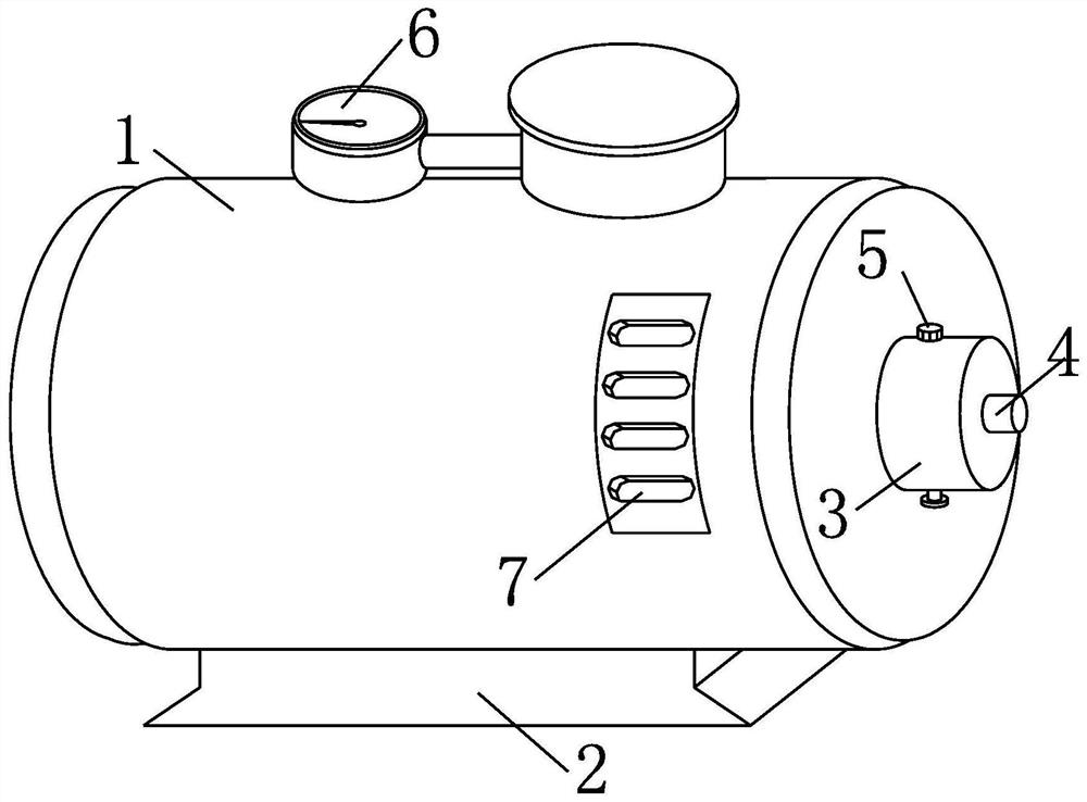
[0002] The compressor is used to increase the air pressure entering the engine and supply the compressed air required for the engine to work. It is a component that uses the rotating blades to do work on the air to increase the air pressure. The traditional compressor has a high working speed and the shaft bearing part It is easy to form an oil film and has good lubrication conditions. For low-speed compressors, due to the friction loss between the shaft and the shaft seat during the rotation of the shaft, it is difficult to work the impeller, and it is necessary to stop frequently for oil lubrication between the shaft and the shaft seat. When the compressor restarts after frequent shutdowns, it is easy to cause shaft wear, reduce the service life of the compressor, and affect the normal operation of the compressor

Method used


Image

  • A low speed compressor lubrication structure
  • A low speed compressor lubrication structure
  • A low speed compressor lubrication structure

Examples


Embodiment Construction

[0027] It should be noted that, in the case of no conflict, the embodiments of the present invention and the features in the embodiments can be combined with each other.

[0028] In describing the present invention, it should be understood that the terms "center", "longitudinal", "transverse", "upper", "lower", "front", "rear", "left", "right", " The orientations or positional relationships indicated by "vertical", "horizontal", "top", "bottom", "inner" and "outer" are based on the orientations or positional relationships shown in the drawings, and are only for the convenience of describing the present invention and Simplified descriptions, rather than indicating or implying that the device or element referred to must have a particular orientation, be constructed and operate in a particular orientation, and thus should not be construed as limiting the invention. In addition, the terms "first", "second", etc. are used for descriptive purposes only, and should not be understood ...


PUM


Abstract

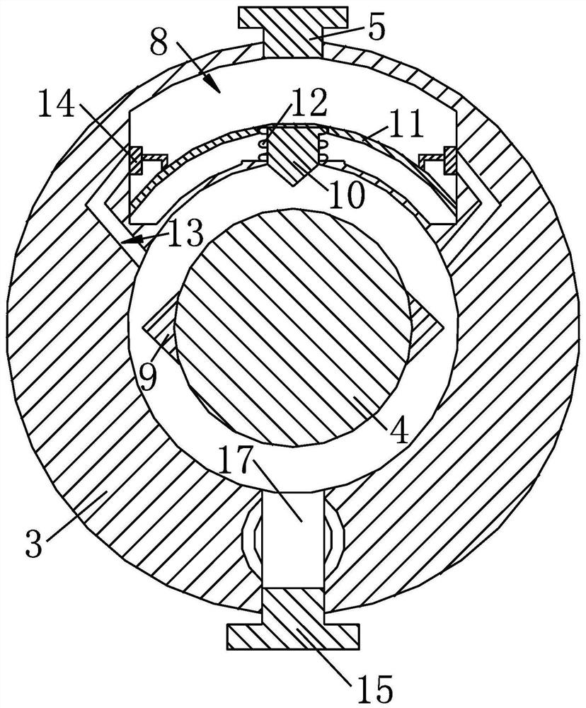
The invention provides a lubricating structure for a low-speed compressor, which includes a compressor body, a base and a shaft seat are fixed on the compressor body, a liquid storage chamber is arranged on the shaft seat, and at least one side of the liquid storage chamber An oil injection hole is provided, and the oil outlet end of the oil injection hole is connected to the gap between the rotating shaft and the shaft seat; a fixed block is fixed on the rotating shaft, and a top block is slidably connected to the shaft seat, and the fixed block The vertical distance between the outer edge and the rotating shaft is greater than the vertical distance between the bottom end of the top block and the rotating shaft; the top of the top block is provided with a seal for opening and closing the oil hole; the present invention uses the fixed block Push the top block up to make the seal close or open the oil injection hole, push the lubricating oil in the liquid storage chamber into the gap between the shaft and the shaft seat through the oil injection hole, and perform intermittent automatic lubrication on the shaft and shaft seat to prevent the rotation of the shaft and the shaft seat. The wear between the shaft seats reduces the wear of the shaft due to frequent shutdowns due to adding lubricating oil.

Description

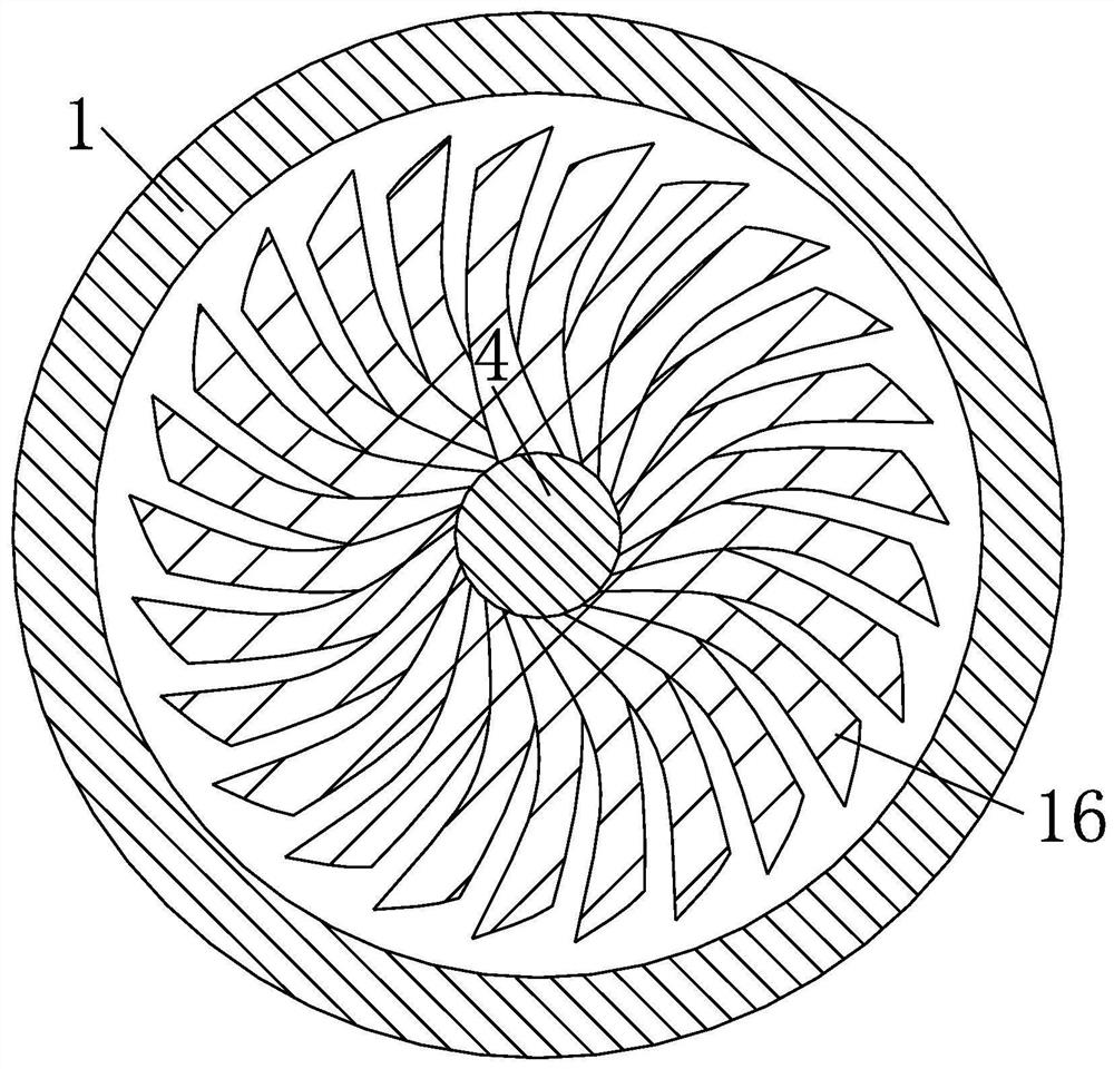
technical field [0001] The invention belongs to the field of electromechanical technology, and in particular relates to a lubricating structure for a low-speed compressor. Background technique [0002] The compressor is used to increase the air pressure entering the engine and supply the compressed air required for the engine to work. It is a component that uses the rotating blades to do work on the air to increase the air pressure. The traditional compressor has a high working speed and the shaft bearing part It is easy to form an oil film and has good lubrication conditions. For low-speed compressors, due to the friction loss between the shaft and the shaft seat during the rotation of the shaft, it is difficult to work the impeller, and it is necessary to stop frequently for oil lubrication between the shaft and the shaft seat. When the compressor restarts after frequent shutdowns, it is easy to cause shaft wear, reduce the service life of the compressor, and affect the no...

Claims


Application Information

Patent Timeline
Patent Type & Authority Patents(China)
IPC IPC(8): F02B39/14F02B39/00F04D29/053F04D29/056F04D29/063
CPCF02B39/14F02B39/00F04D29/063F04D29/056F04D29/053
Inventor 赵力明
Owner CHINA NORTH ENGINE INST TIANJIN
Learn More