
Automobile Brake Pad Wear Monitoring Device

A wear condition and monitoring device technology, applied in the direction of brake types, mechanical equipment, etc., can solve problems such as brake pad wear, automobile safety hazards, etc., and achieve the effect of reasonable structure and layout

Active Publication Date: 2021-05-25
NINGBO HELI BRAKE SYST CO LTD
View PDF0 Cites 0 Cited by
  • Summary
  • Abstract
  • Description
  • Claims
  • Application Information

AI Technical Summary

Problems solved by technology

[0003] When the existing pneumatic disc brake is in use, although it has a braking effect on the tires, it is impossible to know the wear of the two brake pads in time, that is, whether the wear position has reached the maximum amount of wear, thus causing the brake pads to wear out. After severe wear and tear, it is impossible to know in time, which leads to certain safety hazards in the long-distance use of the car

Method used


Image

  • Automobile Brake Pad Wear Monitoring Device
  • Automobile Brake Pad Wear Monitoring Device
  • Automobile Brake Pad Wear Monitoring Device

Examples


Embodiment 1

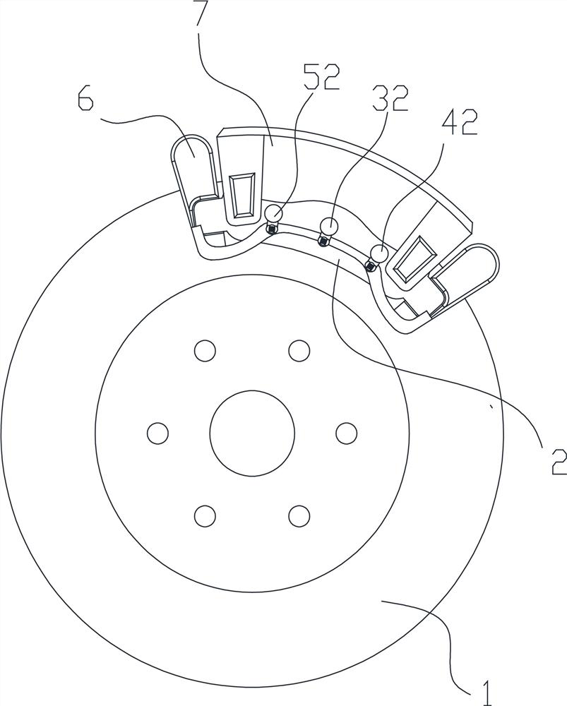
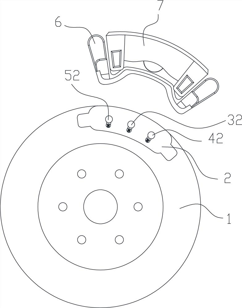
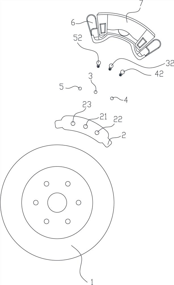
[0032] Embodiment one, such as Figure 7 As shown, the automobile brake brake pad wear monitoring device includes a first observation hole 21 arranged between the inner wall 25 and the outer wall 24 of the brake pad 2, the inner wall 25 is facing the brake disc 1, and the first observation hole 21 is embedded A first observation piece 3 is provided; the first observation piece 3 includes a first end portion 31 facing the outer wall 24 , and the first end portion 31 is located in the first observation hole 21 . Brake pad 2 is installed on the support 6, and is equipped with shield 7. In the process of braking, the constant friction between the brake pad 2 and the brake disc 1 produces consumption, and at the same time, the first observation member 3 will be worn, until the first end 31 is worn and the first observation hole 21 can be worn through. The brake disc 1 can be seen from the outside of the brake pad 2 through the first observation hole 21. When the first end 31 is wo...

Embodiment 2

[0033] Embodiment 2, embodiment 2 is to increase the second observation hole 22 and the second observation member 4 on the basis of the embodiment 1, specifically the second observation hole 22 is also provided between the inner wall 25 and the outer wall 24 of the brake pad 2, The second observation hole 22 is embedded with a second observation piece 4; the second observation piece 4 includes a second end 41 facing the outer wall 24, and the second end 41 is located in the second observation hole 22, such as Figure 8 shown.

[0034] In an embodiment, the distance from the second end 41 to the inner wall 25 is equal to the distance from the first end 31 to the inner wall 25, such as Figure 8 shown. If the wear time of the first end portion 31 and the second end portion 41 differ greatly, it means that the wear of the brake pad 2 is uneven, and the brake pad 2 should be calibrated.

Embodiment 3

[0035] Embodiment 3, the structure of embodiment 3 is basically the same as that of embodiment 2, the difference is that the distance from the second end 41 to the inner wall 25 is smaller than the distance from the first end 31 to the inner wall 25, as Figure 9 shown. When the second observation member 4 is completely worn out, it can be used as a first warning, prompting people to replace the brake pads 2 before the first end portion 31 is worn out.


PUM


Abstract

The device for monitoring the wear condition of automobile brake pads of the present invention includes a first observation hole, and a first observation piece is arranged in the first observation hole; the first observation piece includes a first end facing the outer wall, and the first end is located in the first observation hole. look inside the hole. In addition, a second observation piece is provided. During the braking process, the brake pad and the brake disc are constantly rubbed and consumed, and the first observation piece will be worn at the same time, until the first end of the wear can wear through the first observation hole, so that people can view the outside of the brake pad from the outside. The brake disc is peeped through the first observation hole. When the first end is ground through, it means that the brake pad has been ground to the preset thickness. By presetting the position of the first end in the first observation hole, or by presetting the The length of the first sight can set the wear threshold warning thickness. The second sight piece can judge wear and uneven wear together with the first sight piece. The invention has a reasonable structure and layout, does not need to use professional equipment for detection, and can observe and judge the wear condition of the brake pads from the outside of the brake pads.

Description

technical field [0001] The invention belongs to the field of automobile brakes, in particular to a monitoring device for the wear condition of brake pads of automobile brakes. Background technique [0002] The pneumatic disc brake is installed on the wheel shaft and rotates synchronously with the wheel. The disc brake is mainly divided into: bracket and shield, pin shaft, flange, brake disc, brake pad, caliper. When braking, the brake caliper is clamped The brake disc, the brake disc and the wheel are coaxially fixed, the brake disc and the brake pad contact to produce braking, that is, the caliper generates braking torque under the push of pressure, and the brake pad clamps the brake disc under the push of the piston, braking The moving disc and the wheel decelerate or stop rotating together, and the constant friction between the brake pads and the brake disc produces consumption. In order to ensure the normal braking function, it is necessary to regularly check and replace...

Claims


Application Information

Patent Timeline
Patent Type & Authority Patents(China)
IPC IPC(8): F16D66/02
CPCF16D66/022F16D66/026
Inventor 陈益张文刚
Owner NINGBO HELI BRAKE SYST CO LTD
Learn More