Device for monitoring abrasion condition of brake pad of automobile brake
A wear condition and monitoring device technology, applied in the direction of brake type, mechanical equipment, etc., can solve the problems of brake pad wear and hidden danger of automobile safety, and achieve the effect of reasonable structure and layout.
- Summary
- Abstract
- Description
- Claims
- Application Information
AI Technical Summary
Problems solved by technology
Method used
Image
Examples
Embodiment 1
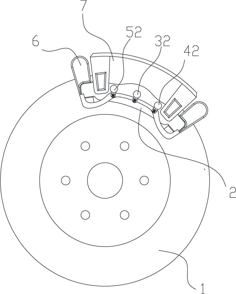
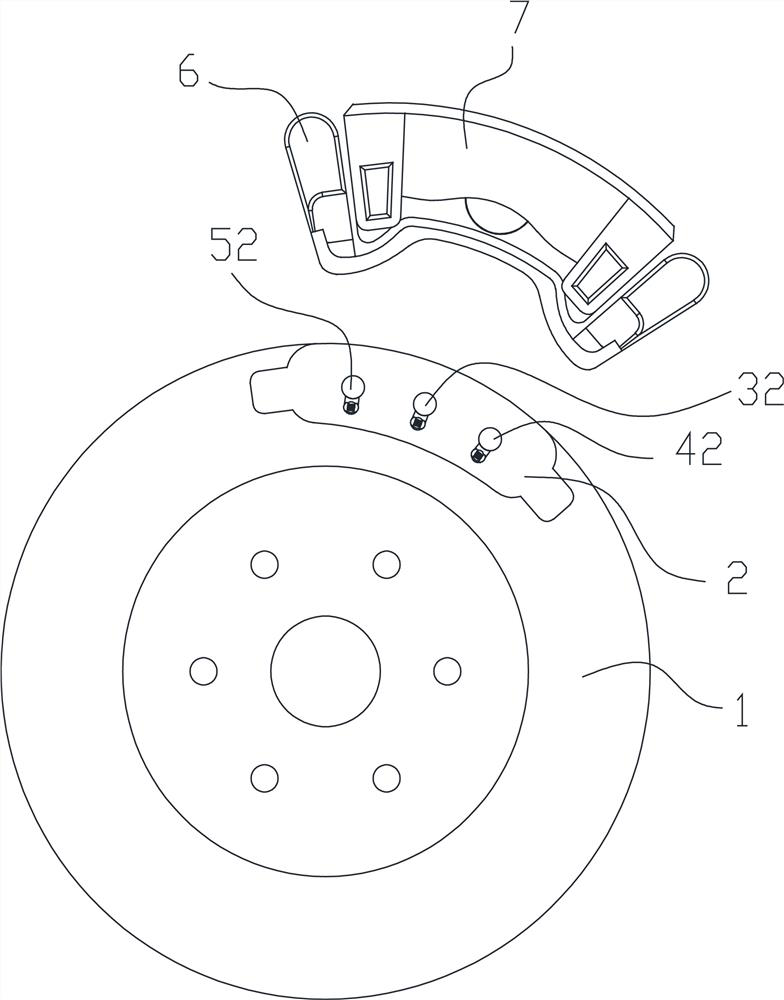
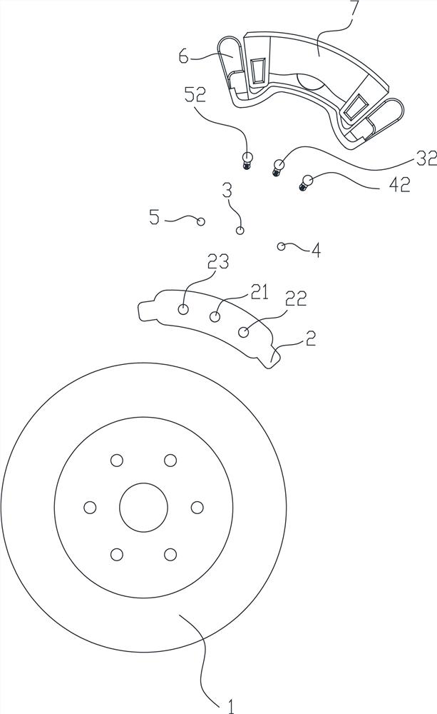
[0032] Embodiment one, such as Figure 7 As shown, the automobile brake brake pad wear monitoring device includes a first observation hole 21 arranged between the inner wall 25 and the outer wall 24 of the brake pad 2, the inner wall 25 is facing the brake disc 1, and the first observation hole 21 is embedded A first observation piece 3 is provided; the first observation piece 3 includes a first end portion 31 facing the outer wall 24 , and the first end portion 31 is located in the first observation hole 21 . Brake pad 2 is installed on the support 6, and is equipped with shield 7. In the process of braking, the constant friction between the brake pad 2 and the brake disc 1 produces consumption, and at the same time, the first observation member 3 will be worn, until the first end 31 is worn and the first observation hole 21 can be worn through. The brake disc 1 can be seen from the outside of the brake pad 2 through the first observation hole 21. When the first end 31 is wo...
Embodiment 2
[0033] Embodiment 2, embodiment 2 is to increase the second observation hole 22 and the second observation member 4 on the basis of the embodiment 1, specifically the second observation hole 22 is also provided between the inner wall 25 and the outer wall 24 of the brake pad 2, The second observation hole 22 is embedded with a second observation piece 4; the second observation piece 4 includes a second end 41 facing the outer wall 24, and the second end 41 is located in the second observation hole 22, such as Figure 8 shown.
[0034] In an embodiment, the distance from the second end 41 to the inner wall 25 is equal to the distance from the first end 31 to the inner wall 25, such as Figure 8 shown. If the wear time of the first end portion 31 and the second end portion 41 differ greatly, it means that the wear of the brake pad 2 is uneven, and the brake pad 2 should be calibrated.
Embodiment 3
[0035] Embodiment 3, the structure of embodiment 3 is basically the same as that of embodiment 2, the difference is that the distance from the second end 41 to the inner wall 25 is smaller than the distance from the first end 31 to the inner wall 25, as Figure 9 shown. When the second observation member 4 is completely worn out, it can be used as a first warning, prompting people to replace the brake pads 2 before the first end portion 31 is worn out.
PUM
 Abstract
Description
Claims
Application Information
 - R&D
- Intellectual Property
- Life Sciences
- Materials
- Tech Scout
- Unparalleled Data Quality
- Higher Quality Content
- 60% Fewer Hallucinations
Browse by: Latest US Patents, China's latest patents, Technical Efficacy Thesaurus, Application Domain, Technology Topic, Popular Technical Reports.
© 2025 PatSnap. All rights reserved.Legal|Privacy policy|Modern Slavery Act Transparency Statement|Sitemap|About US| Contact US: help@patsnap.com


