
Numerical control turret punch press
A technology of CNC turret punch presses and turntables, applied in metal processing, metal processing equipment, manufacturing tools, etc., can solve problems such as the inability to truly reflect the wear of the mold, the inability to identify and judge, and the change of punching force is not obvious. It achieves the effect of being compact and easy to implement, with a large range of jaw stroke formation and compact structure
- Summary
- Abstract
- Description
- Claims
- Application Information
AI Technical Summary
Problems solved by technology
Method used
Image

Examples
Embodiment 1
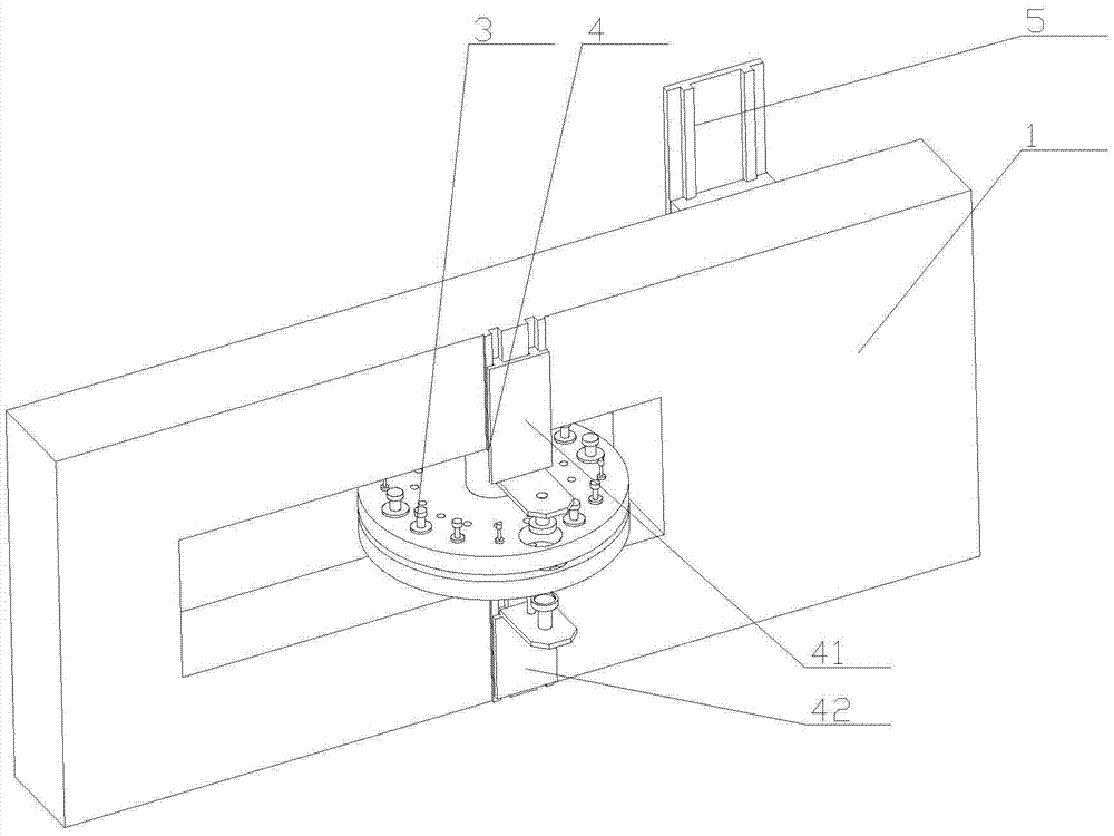
[0062] Embodiment 1: The bottom surface of the horizontal part 1 4122 is fixedly connected with a positioning pin 1 4123, and one side of the upper reserved hole is provided with a pin hole 1 matching with the positioning pin 1, and the horizontal part 2 4222 A positioning pin 2 4223 is also fixedly connected to the top surface of the top surface, and one side of the lower reserved hole is provided with a pin hole 2 adapted to the positioning pin 2.
Embodiment 2
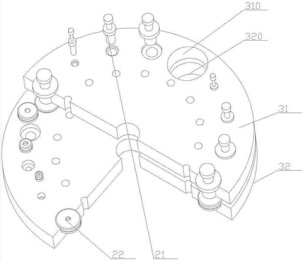
[0063] Embodiment 2: The bottom surface of the horizontal part 1 4122 is also fixedly connected with a positioning sleeve 1, and the positioning sleeve 1 is empty to cover the vision probe 1 411, and the bottom surface of the positioning sleeve 1 is higher than that of the vision probe 1 411. bottom surface, and the outer diameter of positioning sleeve one is smaller than the inner diameter of the upper reserved hole 310;
[0064] The bottom surface of the horizontal part 2 4222 is also fixedly connected with a positioning sleeve 2, the positioning sleeve 2 is empty for the vision probe 2 421, and the top surface of the positioning sleeve 2 is lower than the top surface of the vision probe 2 421 , and the outer diameter of the second positioning sleeve is smaller than the inner diameter of the lower reserved hole 320 . Therefore, while being convenient for positioning, it also has the following characteristics: first, it avoids blocking the visual probe 1 or the visual probe 2...
PUM
 Abstract
Description
Claims
Application Information