
Die wear detecting device of numerical control turret punch press

A technology of CNC turret punch press and detection device, which is applied in the direction of manufacturing tools, metal processing, metal processing equipment, etc., can solve the problems that cannot truly reflect the wear of the die, the change of the punching force is not obvious, and cannot be recognized and judged , to achieve effective detection, compact structure, and easy installation

Active Publication Date: 2016-03-23
江苏扬力数控机床有限公司
View PDF11 Cites 4 Cited by
  • Summary
  • Abstract
  • Description
  • Claims
  • Application Information

AI Technical Summary

Problems solved by technology

[0004] However, in the actual use process, it is found that if the mold is only partially worn, but not broken or damaged, the change of the punching force is not obvious, and the case will not be able to identify and judge, so it cannot truly reflect the wear of the mold Happening

Method used


Image

  • Die wear detecting device of numerical control turret punch press
  • Die wear detecting device of numerical control turret punch press
  • Die wear detecting device of numerical control turret punch press

Examples


Embodiment 1

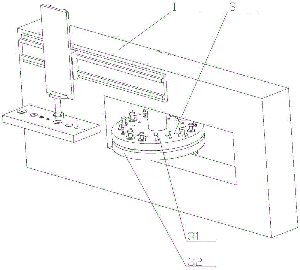
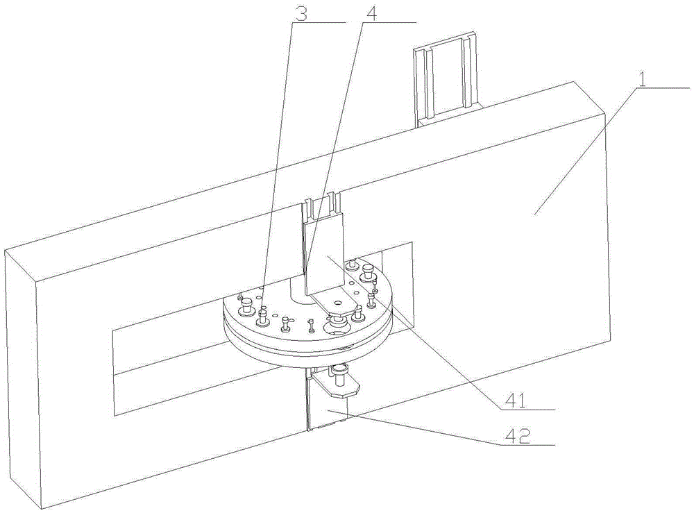
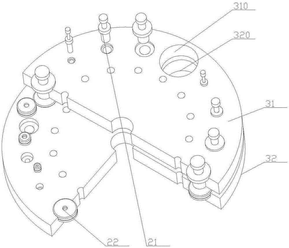
[0027] Embodiment 1: The bottom surface of the horizontal part 1 4122 is fixedly connected with a positioning pin 1 4123, and one side of the upper reserved hole is provided with a pin hole 1 matching with the positioning pin 1, and the horizontal part 2 4222 A positioning pin 2 4223 is also fixedly connected to the top surface of the top surface, and one side of the lower reserved hole is provided with a pin hole 2 adapted to the positioning pin 2.

Embodiment 2

[0028] Embodiment 2: The bottom surface of the horizontal part 1 4122 is also fixedly connected with a positioning sleeve 1, and the positioning sleeve 1 is empty to cover the vision probe 1 411, and the bottom surface of the positioning sleeve 1 is higher than that of the vision probe 1 411. bottom surface, and the outer diameter of positioning sleeve one is smaller than the inner diameter of the upper reserved hole 310;

[0029] The bottom surface of the horizontal part 2 4222 is also fixedly connected with a positioning sleeve 2, the positioning sleeve 2 is empty for the vision probe 2 421, and the top surface of the positioning sleeve 2 is lower than the top surface of the vision probe 2 421 , and the outer diameter of the second positioning sleeve is smaller than the inner diameter of the lower reserved hole 320 . Therefore, while being convenient for positioning, it also has the following characteristics: first, it avoids blocking the visual probe 1 or the visual probe 2...


PUM


Abstract

The invention discloses a die wear detecting device of a numerical control turret punch press, relating to the technical field of automation of numerical control turret punch presses. The die wear detecting device is delicate in structure, high in reliability and convenient to use; and the die wear condition is conveniently detected on the basis of a visual detection technology and on the premise that the main structure of the original turret punch press is remained. The die wear condition is detected by only additionally arranging and forming a reserved hole in a turntable on the basis that the main structure of the existing machine tool is not changed at all; the die wear detecting device is compact and small in structure and is easily realized and conveniently additionally arranged; and the die wear condition is forecasted and evaluated by using the visual detection technology, so that the die wear condition can be more accurately and effectively judged, and the die wear detecting device has actual popularization and application values. The utilization efficiency of the machine tool is not influenced at all, and meanwhile the die wear condition is effectively detected.

Description

technical field [0001] The invention relates to the technical field of automation of a numerically controlled turret punch press, in particular to a die wear detection device for a numerically controlled turret punch. Background technique [0002] At present, CNC turret punch presses are the development trend of automated production lines as the core processing equipment, and because the molds in them are often worn, automatic detection of mold wear has become very necessary and a core technical difficulty. Specifically: 1. Affected by the structural form of the turret punch press, the distance between the upper and lower turntables is narrow, and any detection device is difficult to install, and it is impossible to effectively detect the bottom surface of the upper mold and the top surface of the lower mold. Die change space; 2. The mold has many shapes and sizes and many mold positions, so it is very difficult to measure it with mechanical gauges or instruments. [0003] ...

Claims


Application Information

Patent Timeline
Patent Type & Authority Applications(China)
IPC IPC(8): B21C51/00
CPCB21C51/00
Inventor 胡金龙潘志华孙高平
Owner 江苏扬力数控机床有限公司
Learn More