Novel clamping mechanism for washing machine tripod machining

A clamping mechanism and washing machine technology, applied in metal processing equipment, manufacturing tools, feeding devices, etc., can solve problems such as broken processing drill bits, rotation offset of washing machine tripod, hidden safety hazards, etc., and achieve the effect of guaranteed effect

Inactive Publication Date: 2020-11-17
台州路桥城歌机械有限公司
View PDF17 Cites 0 Cited by
  • Summary
  • Abstract
  • Description
  • Claims
  • Application Information

AI Technical Summary

Problems solved by technology

[0002] The washing machine tripod is the main component that supports the rotation of the drum. The existing washing machine tripod is generally made of cast iron or cast aluminum and then processed. It needs to punch holes at the ends of the three connecting support rods to facilitate its connection with the drum. The bottom is connected, and when the ends of the three connecting support rods are punched, the tripod of the washing machine needs to be fixed first. The existing fixing method is to press and fix by three pressing blocks that press the rotating cylinder. The top surface of the three connecting support rods of the washing machine tripod is pressed against, and the bottom surface of the three connecting support rods and the top surface of the fixed block fixed on the top surface of the installation platform are pressed down by pressing the pressing block of the rotating cylinder When pressing against the top surface of the fixed block for compression, and the fixed block has no side protection mechanism, when the pressure is insufficient, it is easy to cause the washing machine tripod to rotate and deviate during processing, which affects processing, and it is easy to make the processing drill bit Waiting to break, there is a safety hazard

Method used


Image

  • Novel clamping mechanism for washing machine tripod machining
  • Novel clamping mechanism for washing machine tripod machining
  • Novel clamping mechanism for washing machine tripod machining

Examples


Embodiment Construction

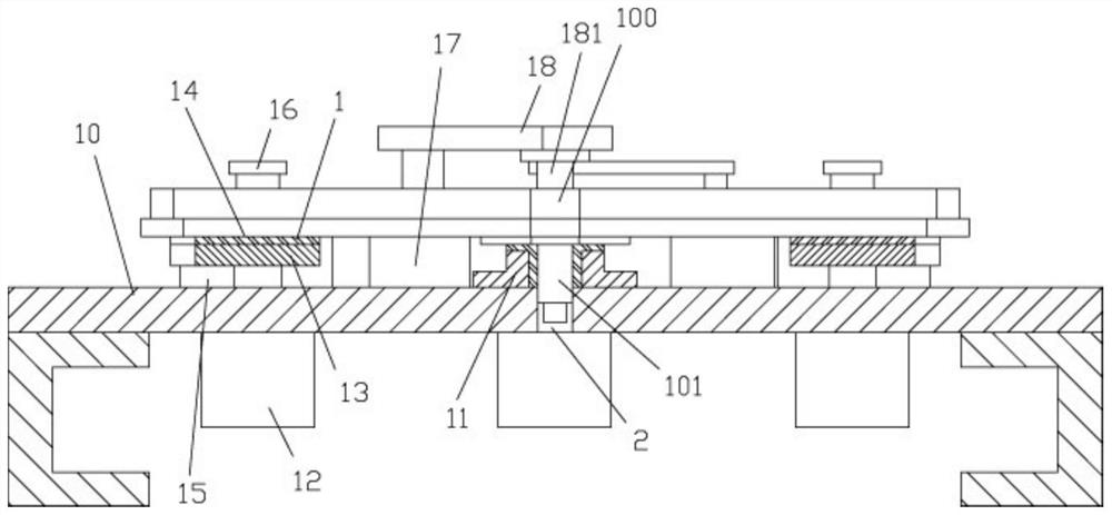
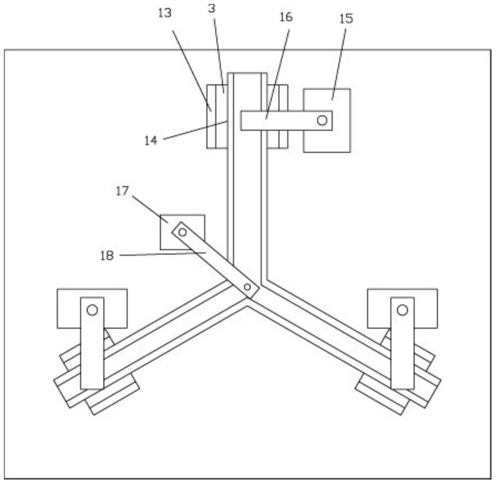
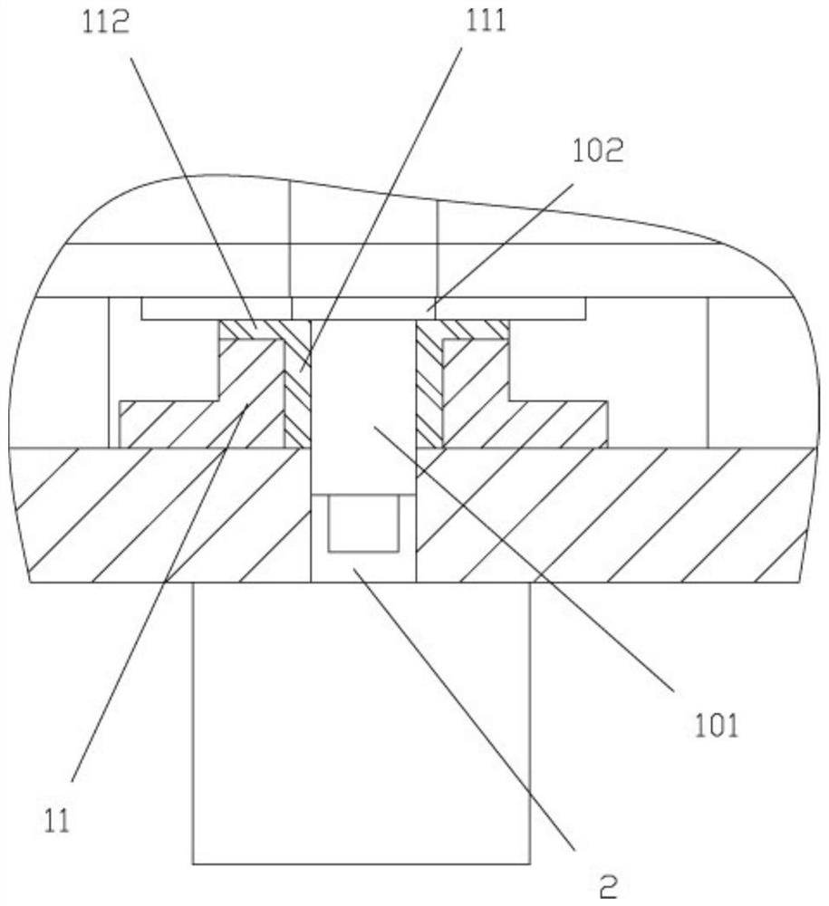
[0018] Examples, see e.g. Figure 1 to Figure 3 As shown, a new type of clamping mechanism for washing machine tripod processing includes a fixed platen 10, the middle top surface of the fixed platen 10 is fixed with a middle shaft placement sleeve 11, and the middle bottom surface of the tripod 100 to be processed is formed. The connecting shaft 101 is inserted into the middle shaft placement sleeve 11;

[0019] The fixed platen 10 is fixed with a bottom pressing cylinder 12 on the bottom surface below the ends of the three connecting support rods of the tripod 100 to be processed, and the push rod of the bottom pressing cylinder 12 passes through the top surface of the fixed platen 10 and is fixed with a The lower pressing block 13 has a slot 14 formed in the middle of the top surface of the lower pressing block 13, and the connecting support rod of the tripod 100 to be processed is inserted in the corresponding slot 14 and pressed against the bottom surface of the slot 14; ...


PUM


Abstract

The invention discloses a novel clamping mechanism for washing machine tripod machining. The novel clamping mechanism comprises a fixing table plate, wherein a middle shaft containing sleeve body is fixed to the top surface of the middle of the fixing table plate, and a connecting shaft formed on the bottom surface of the middle of a tripod to be machined is inserted into the middle shaft containing sleeve body in a sleeved mode; and bottom pressing air cylinders are fixed to the bottom surface, located below the ends of three connecting supporting rods of the tripod to be machined, of the fixing table plate, push rods of the bottom pressing air cylinders penetrate through the top surface of the fixing table plate and are fixedly provided with lower pressing blocks, inserting grooves are formed in the middles of the top surfaces of the lower pressing blocks, and the connecting supporting rods of the tripod to be machined are inserted into the corresponding inserting grooves in a sleeved mode and are pressed against the bottom surfaces of the inserting grooves. According to the novel clamping mechanism, it can be ensured that the tripod to be machined is firmly clamped and cannot rotate, and the follow-up machining effect is ensured.

Description

technical field [0001] The invention relates to the technical field of washing machine household appliances, and more specifically relates to a novel clamping mechanism for washing machine tripod processing. Background technique [0002] The washing machine tripod is the main component that supports the rotation of the drum. The existing washing machine tripod is generally made of cast iron or cast aluminum and then processed. It needs to punch holes at the ends of the three connecting support rods to facilitate its connection with the drum. The bottom is connected, and when the ends of the three connecting support rods are punched, the tripod of the washing machine needs to be fixed first. The existing fixing method is to press and fix by three pressing blocks that press the rotating cylinder. The top surface of the three connecting support rods of the washing machine tripod is pressed against, and the bottom surface of the three connecting support rods and the top surface ...

Claims


Application Information

Patent Timeline
Patent Type & Authority Applications(China)
IPC IPC(8): B21D28/24B21D43/00
CPCB21D28/24B21D43/003
Inventor 李庭锋
Owner 台州路桥城歌机械有限公司
Why Eureka
Try Eureka