
A fatigue test device and method thereof

A fatigue test and loading device technology, applied in the direction of aircraft component testing, etc., can solve the problems of lack and difficulty in obtaining effective test results, and achieve the effect of effective test results

Active Publication Date: 2022-02-22
CHINA AIRPLANT STRENGTH RES INST
View PDF0 Cites 0 Cited by
  • Summary
  • Abstract
  • Description
  • Claims
  • Application Information

AI Technical Summary

Problems solved by technology

[0004] When performing fatigue tests on the rear fuselage structure of an aircraft, how to accurately simulate its loaded state during flight is of great significance for obtaining accurate test results. At present, when performing fatigue tests on the rear fuselage structure of an aircraft, there is a lack of accurate simulation It is an effective method for the rear fuselage structure of the aircraft to be loaded under the flight state, and it is difficult to obtain effective test results

Method used


Image

  • A fatigue test device and method thereof
  • A fatigue test device and method thereof

Examples


Embodiment Construction

[0051] In order to make the technical solution of the present application and its advantages clearer, the technical solution of the present application will be further clearly and completely described in detail below in conjunction with the accompanying drawings. It can be understood that the specific embodiments described here are only part of the application Examples are only used to explain the present application, not to limit the present application. It should be noted that, for the convenience of description, only the parts related to the present application are shown in the drawings, and other relevant parts can refer to the general design. In the case of no conflict, the embodiments in the application and the technologies in the embodiments Features can be combined with each other to obtain new embodiments.

[0052] In addition, unless otherwise defined, the technical terms or scientific terms used in the description of the application shall have the usual meanings und...


PUM


Abstract

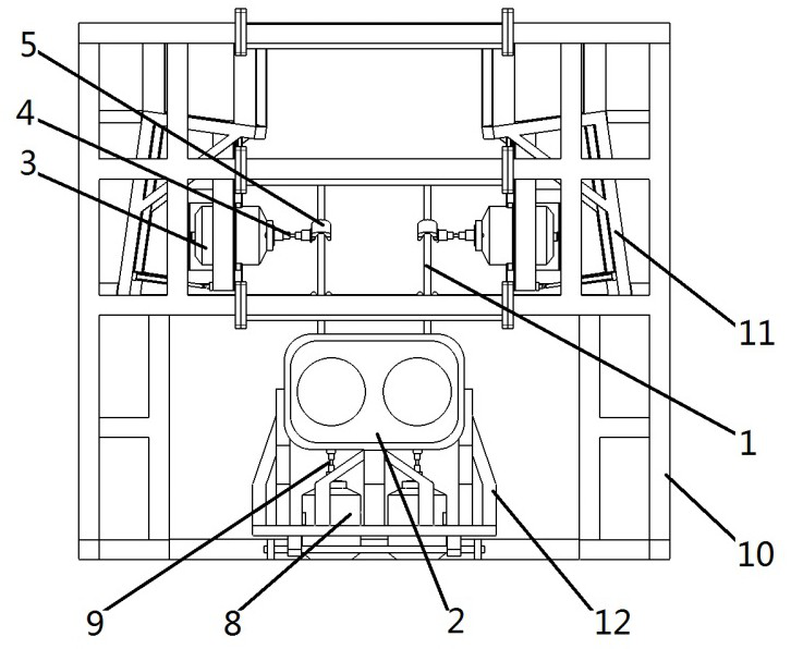
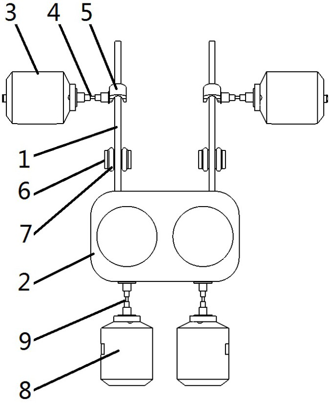
The application belongs to the technical field of aircraft rear fuselage structure fatigue test, and specifically relates to a fatigue test device, including: two vertical tail vibration load loading devices, and each vertical tail vibration load loading device is used to connect to the aircraft rear fuselage structure correspondingly one vertical tail, to apply vibration load to the corresponding vertical tail; two vertical tail aerodynamic load loading devices, each vertical tail aerodynamic load loading device is used to correspond to a vertical tail connected to the rear fuselage structure of the The aerodynamic load is applied to the tail; the engine frame vibration load loading device is used to connect the engine frame of the rear fuselage structure of the aircraft to apply vibration loads to the engine frame. In addition, it relates to a fatigue test method, which is implemented based on the above-mentioned fatigue test device, and can obtain relatively more effective test results when applied to the fatigue test of the aircraft rear fuselage structure.

Description

technical field [0001] The application belongs to the technical field of fatigue test of aircraft rear fuselage structure, and in particular relates to a fatigue test device and a method thereof. Background technique [0002] At present, when conducting aircraft fatigue tests, the dynamic characteristics of the aircraft structure during flight are mostly ignored, and the load environment of the aircraft structure during flight cannot be truly simulated, resulting in deviations between the test structure and the actual situation. [0003] The rear fuselage structure of the aircraft includes the engine frame and two opposite vertical fins, which are subjected to complex loads during the flight of the aircraft. Among them, the engine frame bears the vibration load caused by the engine when the aircraft is flying, and the vertical fin bears the vibration load caused by the air flow passing through its surface. Vibration loads of eddy currents, as well as withstand aerodynamic lo...

Claims


Application Information

Patent Timeline
Patent Type & Authority Patents(China)
IPC IPC(8): B64F5/60
CPCB64F5/60
Inventor 王彬文张治君潘凯何石王龙
Owner CHINA AIRPLANT STRENGTH RES INST
Learn More