A composite material rudder surface load loading device

A composite material and loading device technology, which is used in measuring devices, analyzing materials, and testing the strength of materials by applying a stable torsion force, can solve the problems of structural damage of the rudder surface, inability to apply, and the test cannot be carried out normally, so as to achieve uniform loading, Avoid centralized loading effects

Active Publication Date: 2016-04-27
NAT UNIV OF DEFENSE TECH
View PDF8 Cites 0 Cited by
  • Summary
  • Abstract
  • Description
  • Claims
  • Application Information

AI Technical Summary

Problems solved by technology

[0006] Although the structure of the single-point loading method is simple, there is a difference between this loading method and the actual bearing method of the rudder surface (the actual rudder surface bears the surface load instead of the single-point load), and the single-point loading is likely to cause a large local stress at the loading point and deformation, resulting in damage to the rudder surface structure
[0007] Although the surface loading method using canvas is close to the actual force-bearing form of the structure, the bonding strength of the glue used to paste the canvas limits the load on the rudder surface. Limited time, the canvas is prone to debonding during the loading process, resulting in the test not being able to proceed normally
[0008] In addition, the single-point loading and canvas loading methods, the loading objects are limited to materials with high rigidity such as metal, and these two loading methods cannot be applied to materials with weaker strength such as fiberglass for the rudder surface

Method used


Image

  • A composite material rudder surface load loading device
  • A composite material rudder surface load loading device
  • A composite material rudder surface load loading device

Examples


Embodiment Construction

[0027] The present invention will be described in detail below in conjunction with the accompanying drawings.

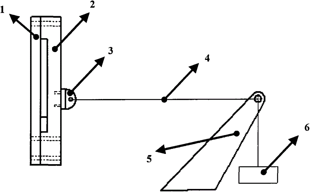
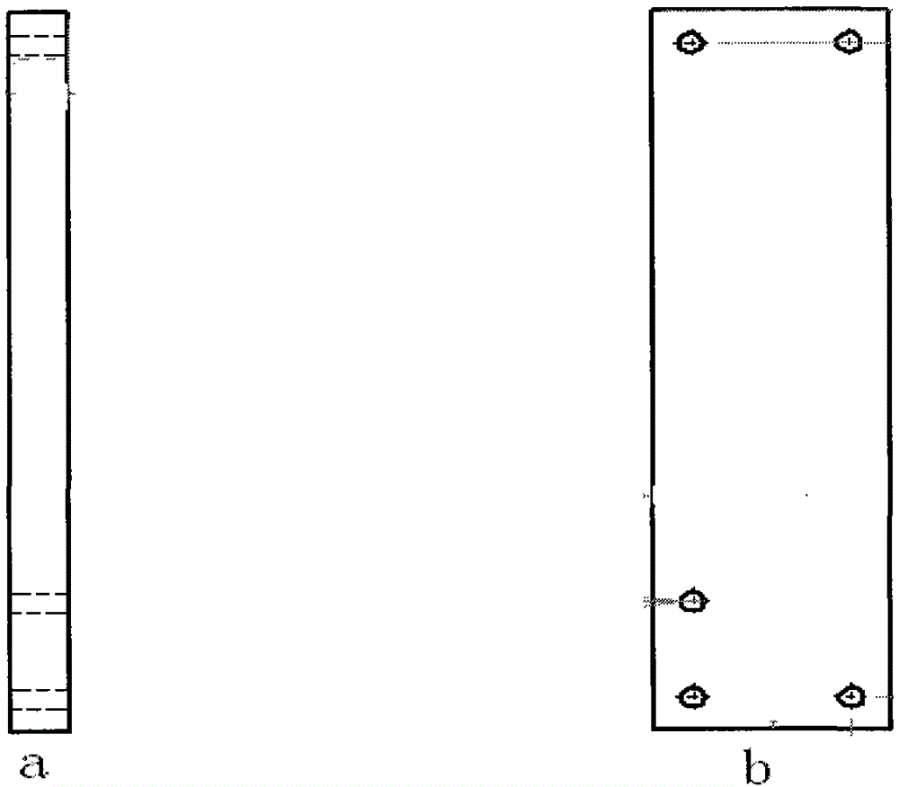
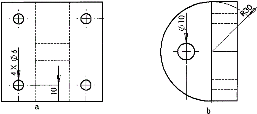
[0028] The present invention realizes the joint loading of the rudder surface bending moment and torque by designing a set of rudder surface loading fixtures, such as Figure 1 ~ Figure 4 shown.

[0029] Install two loading fixtures on both sides of the air rudder. The inner surface of the two fixtures is consistent with the outer surface of the air rudder, so as to realize the close fit between the fixture and the air rudder, ensure uniform loading, and avoid the shaking of the air rudder. The two clamps are fixed to each other.

[0030] One side of any fixture is fixed on the adapter block, and the position of the adapter block is located at the pressure center of the rudder surface, which can accurately simulate the bending moment and torque on the rudder surface.

[0031] One end of the steel rope is fixed to the adapter block, and the other end passes through ...


PUM


Abstract

The invention provides a rudder plane loading device for a composite material. Two loading fixtures (1 and 2) are mounted on the two sides of the rudder plane of the composite material; the inner shaping planes of the two fixtures are the same as the outer shaping plane of an air rudder; an adapting block (3) is fixed on one side of one of the fixtures, and is positioned at the pressed center of the rudder plane; one end of a steel rope (4) is fixed at the adapting block (3), and the other end of the steel rope (4) is tied to a tensile force supply device (6). The loading device can be used for combined loading for a load with large bending moment and torque within the bearing range of strong rigidity and can be used for combing loading for torque and bending moment for the rudder plane made of composite material.

Description

technical field [0001] The invention relates to the technical field of hypersonic aircraft, in particular to a joint loading method of composite material rudder surface torque and bending moment load. Background technique [0002] The air rudder of the hypersonic vehicle not only bears the bending moment but also the torque load during the actual flight. Under the actual flight load conditions, evaluate the anti-bending moment, anti-torque ability of the air rudder component unlocking mechanism, and the unlocking ability under load conditions. It is the key issue to determine whether the air rudder can work stably. [0003] The bending moment borne by the air rudder is usually to load a normal force on the rudder surface, and make the resultant force point of the normal force pass through the pressure center of the rudder surface; for the loading of torque, it is usually to load a normal force on the rudder surface, through The normal force distribution of the rudder surfac...

Claims


Application Information

Patent Timeline
Patent Type & Authority Patents(China)
IPC IPC(8): G01N3/20G01N3/22G01N3/04
Inventor 夏智勋罗世彬王中伟王德全柳军郭振云明志茂曾庆华刘冰金亮李洁李大鹏黄伟黄哲志董荣华贾零祁罗文彩
Owner NAT UNIV OF DEFENSE TECH
Why Eureka
Try Eureka