Leg supporting device on medical traction equipment

A technology of leg support and traction equipment, applied in passive exercise equipment, physical therapy and other directions, can solve problems such as damage to rotating joints, and achieve the effect of enhancing support strength

Inactive Publication Date: 2020-11-20
苏州哲思达智能设备科技有限公司
View PDF7 Cites 3 Cited by
  • Summary
  • Abstract
  • Description
  • Claims
  • Application Information

AI Technical Summary

Problems solved by technology

At the same time, in the process of rehabilitation physiotherapy, physiotherapy robots have also emerged as the times require. At present, in traction and stretching rehabilitation physiotherapy, a robot is used. The robot is equipped with two supporting pieces, and the supporting pieces are equipped with leg brackets. A pulling device is installed at the end of the supporting tube, which can pull and stretch the leg; the supporting tube needs to be able to be rotated and positioned so that the patient's leg can be raised; the end of the supporting tube connected to the robot is equipped with a rotary joint , and the end of the supporting piece away from the robot is generally suspended; when the patient is pulling and stretching, the weight of the patient's legs acts on the supporting piece, and the suspended supporting piece acts on the connection between the supporting piece and the robot. At the rotating joint, it is easy to cause damage to the rotating joint

Method used


Image

  • Leg supporting device on medical traction equipment
  • Leg supporting device on medical traction equipment
  • Leg supporting device on medical traction equipment

Examples


Embodiment

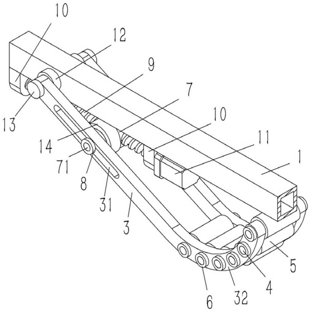
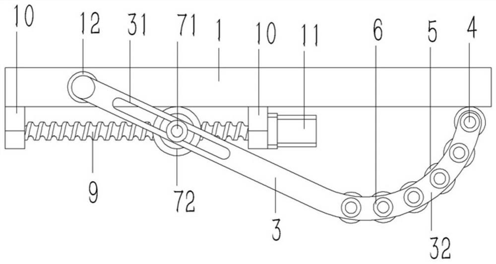
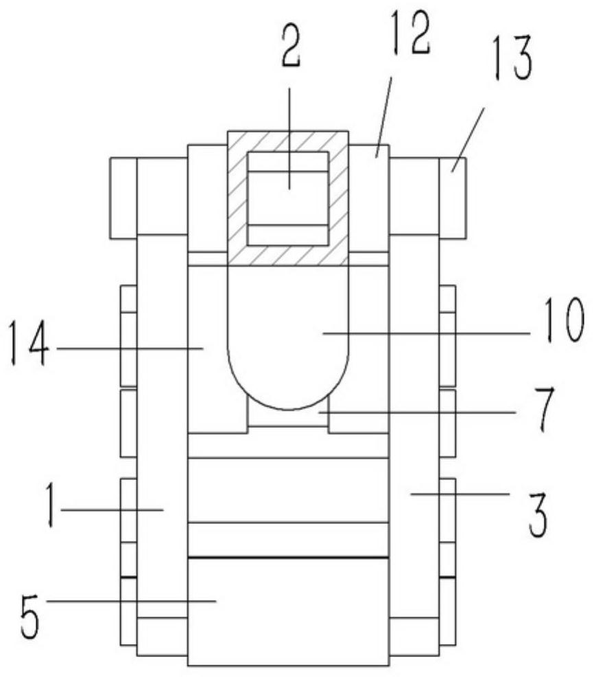
[0017] Example: see Figures 1 to 3 As shown, a leg support device on a medical traction device includes a rectangular tubular support rod 1, and a longitudinal connecting shaft 2 is inserted into the supporting rod 1, and the two ends of the connecting shaft 2 protrude from the supporting rod 1 There are rod-shaped legs 3 inserted in the outer wall of the outer wall, and the lower ends of the legs 3 are bent to form arc-shaped support parts 32. Several roller sleeves 5 are inserted between the support parts 32, and the roller sleeves 5 are distributed on the support rod 1. The lower side of the pin shaft 4 is plugged with a pin shaft 4, and the two ends of the pin shaft 4 pass through the support part 32 to insert and fix the limit sleeve 6; the support leg 3 is formed with a guide groove 31, and a drive is inserted between the support legs 3. Axle 7, the middle part of driving shaft 7 is screwed with horizontal leading screw 9, and the two ends of leading screw 9 are hinged ...


PUM


Abstract

The invention discloses a leg supporting device on medical traction equipment. The device comprises a rectangular tubular bearing rod, wherein a longitudinal connecting shaft is inserted into the bearing rod, two ends of the connecting shaft stretch out of the outer wall of the bearing rod to be sleeved with rod-shaped supporting feet, lower ends of the supporting feet are bent to form arc-shapedsupporting parts, a plurality of roller sleeves are connected between the supporting parts in an inserted mode, the roller sleeves are distributed on the lower sides of the bearing rod and connected with pin shafts in an inserted mode, and two ends of the pin shafts penetrate through the supporting parts to be connected and fixed with limiting sleeves in an inserted mode; guide grooves are formedin the supporting feet, a driving shaft is inserted between the supporting feet, a transverse lead screw is connected to the middle of the driving shaft in a threaded mode, two ends of the lead screware hinged to hinged supports, and the hinged supports are fixed to the lower end face of the bearing rod; one end of the lead screw is fixedly connected with a rotating shaft of a motor, and the motor is fixed to the hinged support; guiding shafts are formed at two ends of the driving shaft and penetrate through the guiding grooves of the supporting feet to be fixedly sleeved with positioning sleeves.

Description

technical field [0001] The invention relates to the technical field of medical equipment, in particular to a leg support device on medical traction equipment. Background technique [0002] Medical robots refer to robots used for medical treatment or auxiliary medical treatment in hospitals and clinics. It is an intelligent service robot, which can independently program the operation plan, determine the action program according to the actual situation, and then turn the action into the movement of the operating mechanism. At the same time, in the process of rehabilitation physiotherapy, physiotherapy robots have also emerged as the times require. At present, in traction and stretching rehabilitation physiotherapy, a robot is used. The robot is equipped with two supporting pieces, and the supporting pieces are equipped with leg brackets. A pulling device is installed at the end of the supporting tube, which can pull and stretch the leg; the supporting tube needs to be able to...

Claims


Application Information

Patent Timeline
Patent Type & Authority Applications(China)
IPC IPC(8): A61H1/02
CPCA61H1/0237A61H2201/164A61H2201/1642A61H2205/10
Inventor 胡惠娟
Owner 苏州哲思达智能设备科技有限公司
Why Eureka
Try Eureka