Multi-edge bending machine

A bending machine, multilateral technology, applied in the field of bending machines, can solve the problems of complicated adjustment, waste of time, inconvenient operation, etc., and achieve the effect of increasing stability and accurate power transmission

Active Publication Date: 2015-04-01
佛山市顺德区胜海五金制品有限公司
View PDF6 Cites 4 Cited by
  • Summary
  • Abstract
  • Description
  • Claims
  • Application Information

AI Technical Summary

Problems solved by technology

Existing bending machines need to adjust the distance between the mold and the bending mold when bending thin plates and thick plates. Most of them need to be adjusted manually, or additional mechanisms are added to adjust. The adjustment is complicated, inconvenient to operate, and wasteful. time

Method used


Image

  • Multi-edge bending machine
  • Multi-edge bending machine
  • Multi-edge bending machine

Examples


Embodiment Construction

[0019] A preferred embodiment of the present invention will be further described below in conjunction with the accompanying drawings, so as to help understand the content of the present invention.

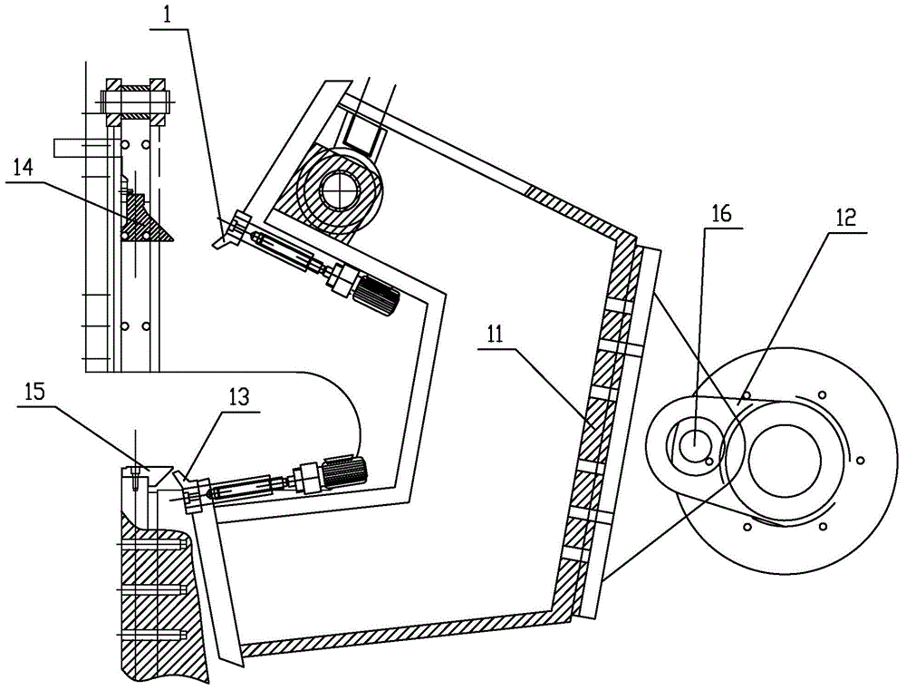
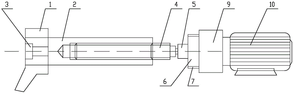
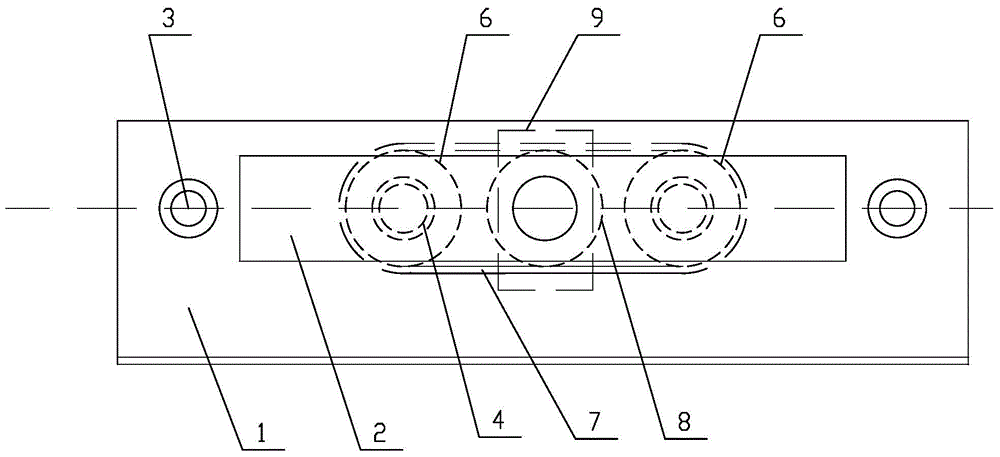
[0020] Such as Figure 1 to Figure 3 As shown, the present invention includes a knife rest 11 that is integrally shaped as a "concave", and the legs on both sides of the knife rest 11 are slightly opened outwards. The first upper mold 1 is arranged at the apex of the inner side of the leg, and the first lower mold 13 is arranged at the apex of the inner side of the lower leg of the knife rest 11, and the mold and the knife rest 11 are connected by bolts 3; the first upper mold 1 and the first lower mold 13 A rectangular through hole is arranged in the middle, and a rectangular push block 2 matched with it is arranged in the through hole. The left end face of the push block 2 does not exceed the left end face of the mould; A rectangular through hole matched with the push block 2 is...


PUM


Abstract

The invention discloses a multi-edge bending machine and relates to bending machines. The multi-edge bending machine comprises a concave knife rest, supporting legs at the two sides slightly stretch towards the outside, the outer side of the middle of the knife rest is connected with a swing arm through a shaft, a first upper die is arranged at the vertex of the inner side of the upper supporting leg of the knife rest, a first lower die is arranged at the vertex of the inner side of the lower supporting leg of the knife rest, the dies are connected with the knife rest through bolts, polygonal through holes are formed in the middles of the first upper die and first lower die, polygonal push blocks matched with the through holes are arranged therein, one head face of each push block does not surpass the left head face of the corresponding die, and the end of each push block far away from the corresponding die is connected with at least one push device. After a sheet bends a certain angle, the push devices are started to push the push blocks to move towards the sheet and push one bent edge of the sheet to continue to get close to the other bent edge to realize the larger than 90 degrees bend angle of the sheet.

Description

technical field [0001] The invention relates to a bending machine, in particular to a multilateral bending machine. Background technique [0002] A bending machine is a machine capable of bending thin plates. Existing bending machines need to adjust the distance between the mold and the bending mold when bending thin plates and thick plates. Most of them need to be adjusted manually, or additional mechanisms are added to adjust. The adjustment is complicated, inconvenient to operate, and wasteful. time. A Chinese patent application for a bending machine, application number 201310295375.0, includes a feeding mechanism clamping device, a bending mechanism and a balance spring device. The feeding mechanism clamping device includes a U-shaped beam, a cylinder, a pressure rod, a bearing, a servo motor, the first The rotating chassis and the second rotating chassis, the upper end of the U-shaped beam is equipped with a cylinder, the pressure rod is installed on the cylinder, the...

Claims


Application Information

Patent Timeline
Patent Type & Authority Applications(China)
IPC IPC(8): B21D5/04
CPCB21D5/04
Inventor 涂开德
Owner 佛山市顺德区胜海五金制品有限公司
Why Eureka
Try Eureka