Sliding plate for automobile chassis maintenance
A technology of automobile chassis and skateboards, which is applied to workshop equipment, manufacturing tools, etc., can solve the problems of wasting time, inconvenient fixing of skateboards, and difficult operation by staff, and achieve the effects of simple and convenient operation, improved comfort, and improved maintenance speed
- Summary
- Abstract
- Description
- Claims
- Application Information
AI Technical Summary
Problems solved by technology
Method used
Image

Examples
Embodiment Construction
[0026] In order to make the technical means, creative features, goals and effects achieved by the present invention easy to understand, the present invention will be further described below in conjunction with specific embodiments.
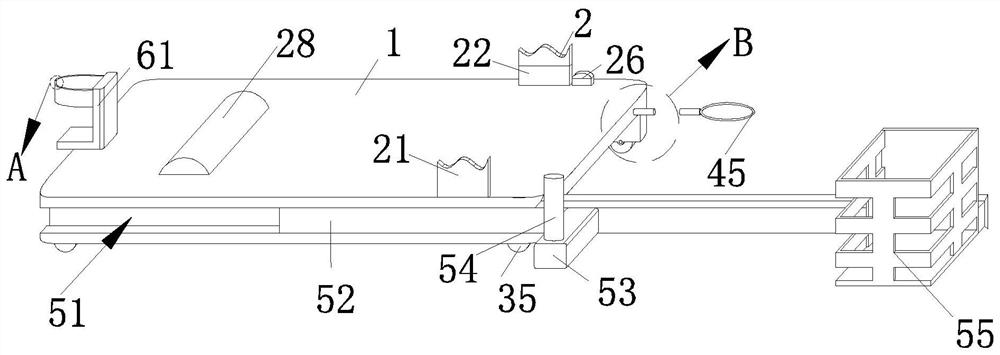
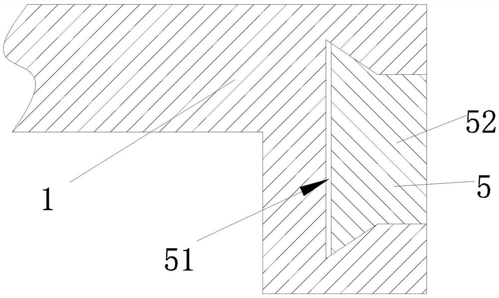
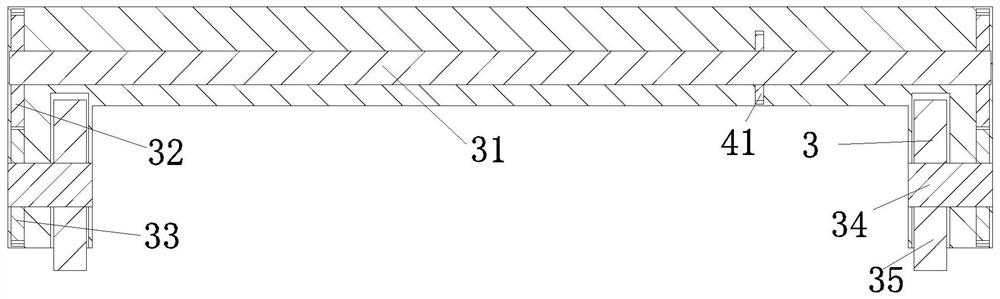
[0027] Such as Figure 1-Figure 8 As shown, a kind of skateboard for automobile chassis maintenance according to the present invention includes a skateboard body 1, a fixing structure 2, a driving structure 3, a limit structure 4, a storage structure 5 and an installation structure 6; The fixed structure 2 whose waist is fixed on the skateboard body 1 is arranged on the top of the skateboard body 1; the driving structure 3 for moving the skateboard body 1 is provided with two groups, and the driving structure 3 is arranged on the Both sides of the bottom end of the skateboard body 1; one end of the limiting structure 4 for limiting the driving structure 3 is arranged inside the skateboard body 1, and the other end of the limiting structure 4 is ar...
PUM
 Abstract
Description
Claims
Application Information
PatSnap Eureka turns technology decisions into work you can execute. Powered by our Innovation Knowledge Graph, it runs expert workflows across engineering, life sciences, materials and intellectual property. Get your review-ready output in minutes.


