Compressor and air conditioner

A technology for compressors and compression chambers, which is applied in the field of compressors, and can solve problems such as sudden changes in the exhaust speed of compressors and sudden changes in the area of ​​the exhaust port, so as to achieve the effects of improving energy efficiency, improving reliability and avoiding large power consumption

Active Publication Date: 2020-11-20
GREE ELECTRIC APPLIANCES INC
View PDF10 Cites 2 Cited by
  • Summary
  • Abstract
  • Description
  • Claims
  • Application Information

AI Technical Summary

Problems solved by technology

[0011] Therefore, the technical problem to be solved by the present invention is to overcome the defect that the compressor in the prior art has a sudden change

Method used


Image

  • Compressor and air conditioner
  • Compressor and air conditioner
  • Compressor and air conditioner

Examples


Embodiment Construction

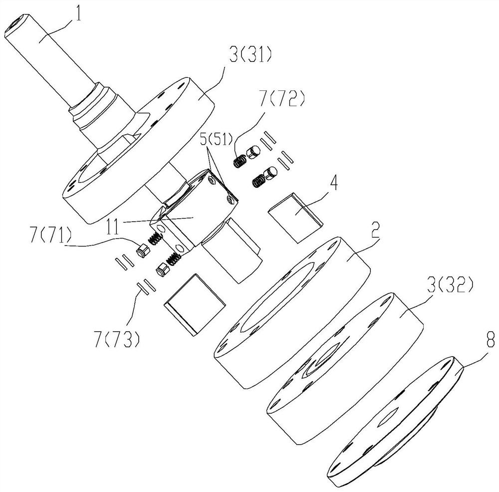
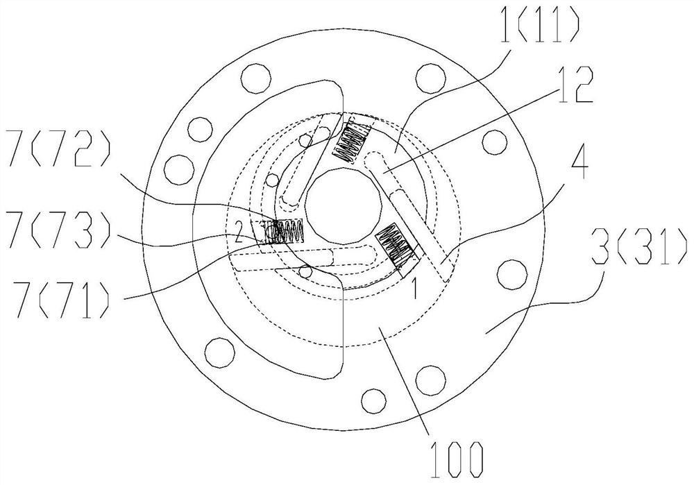
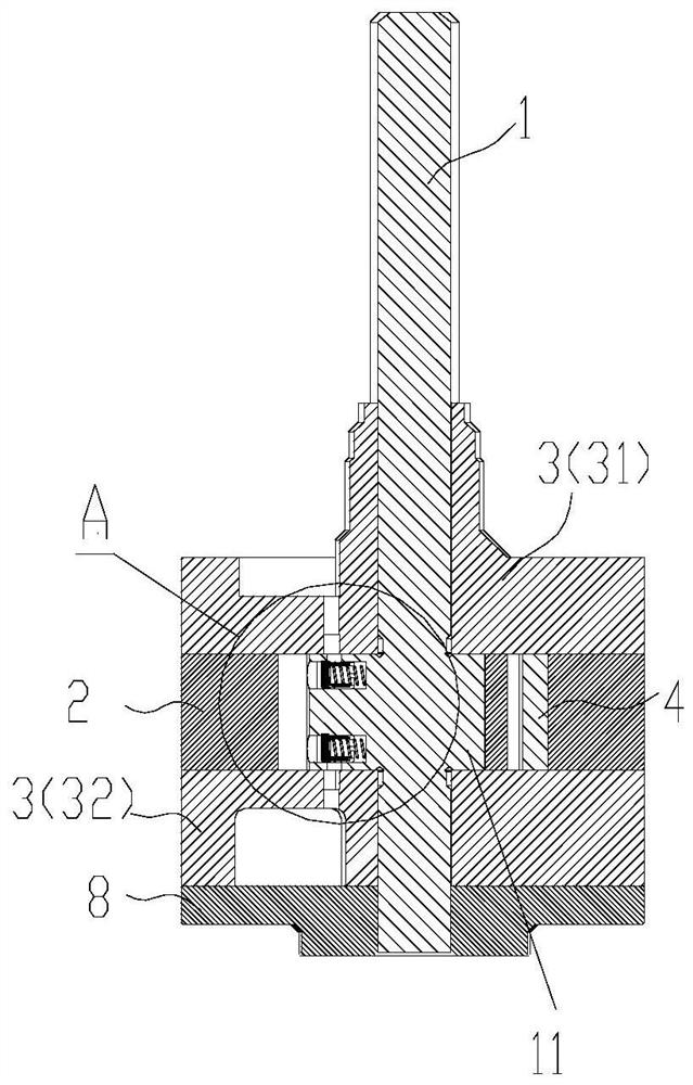
[0048] Such as Figure 1-10 As shown, the present invention provides a compressor, which includes:

[0049] The main shaft 1, the cylinder 2, the flange 3 and the sliding plate 4, the main shaft 1 includes a convex portion 11, the convex portion 11, the cylinder 2, the flange 3 and the sliding plate 4 jointly form a compression chamber 100 , the convex portion 11 is provided with at least one main shaft exhaust port 5 corresponding to each of the compression chambers 100, and the flange 3 is provided with a flange exhaust port 6, (preferably the flange row The air port is arranged opposite to the exhaust port of the main shaft in the radial direction, which can ensure that the flange exhaust port communicates with the exhaust port of the main shaft in the radial direction), and one end of each of the main shaft exhaust ports 5 is connected to the exhaust port of the main shaft. The compression chamber 100 communicates, and the other end can communicate with the flange exhaust...


PUM


Abstract

The invention provides a compressor and an air conditioner. The compressor includes a main shaft, a cylinder, a flange and a sliding vane; the main shaft includes a convex part; the convex part, the cylinder, the flange and the sliding vane together form a compression chamber; at least one main shaft exhaust port is arranged on the convex part corresponding to each compression chamber; a flange exhaust port is arranged on the flange; one end of each main shaft exhaust port is connected to the compression chamber, and the other end can be connected to the flange exhaust port for exhaust duringthe rotation of the main shaft; an exhaust valve assembly is arranged in the main shaft exhaust port; and the exhaust valve assembly can automatically exhaust according to the pressure in the compression chamber. According to the invention, the structure design of the main shaft exhaust port, the exhaust valve assembly and the flange exhaust port is adopted, and therefore, the invention effectively ensures that the number and areas of the exhaust ports in each compression chamber are fixed, meets the compressor exhaust speed requirements, and can ensure that the compressor operates normally under all working conditions and the exhaust speed continuously changes.

Description

technical field [0001] The invention relates to the technical field of compressors, in particular to a compressor and a compressor. Background technique [0002] Patent No. 201510044276.4 discloses a compressor exhaust structure, through which the exhaust channel 30 on the main shaft communicates with the diversion channel 20 on the flange to realize exhaust at the end of the compressor. The main exhaust is realized through the exhaust port 10 on the flange. [0003] The patent No. 201710916718.9 proposes a compressor structure, in which the main exhaust port involved adopts the same principle as the patent 201510044276.4. In order to ensure that the exhaust port area of ​​the compressor is as large as possible and reduce the exhaust loss, it is required When the slide sweeps through the exhaust port, it must completely cover the exhaust port. Therefore, when the exhaust port is increased, a diamond-shaped exhaust port structure is required. [0004] But there are two prob...

Claims


Application Information

Patent Timeline
IPC IPC(8): F04C18/344F04C29/00F04C29/12
CPCF04C18/3445F04C29/00F04C29/128F04C2240/60
Inventor 罗发游万鹏凯苏永强何洋吴飞任丽萍
Owner GREE ELECTRIC APPLIANCES INC
Why Eureka
Try Eureka