Pressure gauge with protective device

A technology of protective device and pressure gauge, which is applied in the direction of measuring device, measuring fluid pressure, measuring force, etc., can solve the problems of insufficient protective performance of the pressure gauge, reducing the service life of the pressure gauge, unable to protect the pressure gauge, etc., and achieves a simple and good structure. protective effect, protective effect

Active Publication Date: 2020-11-20
上海精普机电科技有限公司
View PDF10 Cites 1 Cited by
  • Summary
  • Abstract
  • Description
  • Claims
  • Application Information

AI Technical Summary

Problems solved by technology

[0003] At present, the external protection performance of the pressure gauge is insufficient, and the pressure gauge cannot be fully protected, which may damage the pressure gauge, thereby reducing the service life of the pressure gauge. The body is installed on the pressure gauge by fixing the ferrule with bolts, but after the installation, the pressure gauge needs to disassemble the cover body during its operation and maintenance, and the operation is more troublesome

Method used


Image

  • Pressure gauge with protective device
  • Pressure gauge with protective device
  • Pressure gauge with protective device

Examples


Embodiment 1

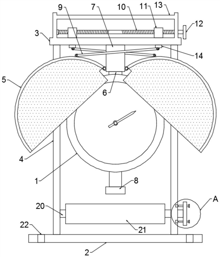
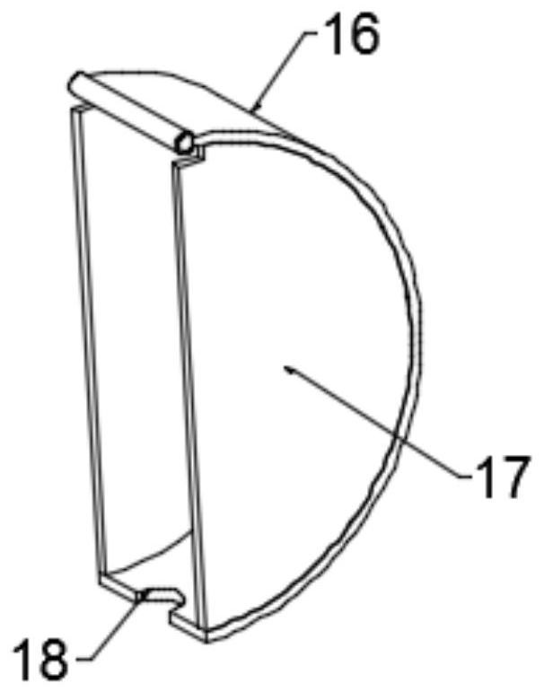
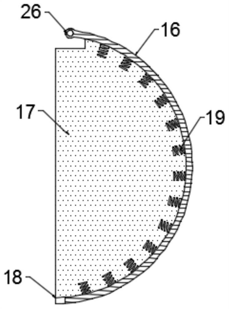
[0025] see Figure 1~4 , in an embodiment of the present invention, a pressure gauge with a protective device includes a pressure gauge body 1 and a fixed base plate 2, the upper end surface of the fixed base plate 2 is fixedly connected with a side support rod frame 4 and the top end of the side support rod frame 4 is provided with Install the top plate 3, the middle part of the lower end surface of the installation top plate 3 is provided with a mounting screw sleeve 7, the top end of the pressure gauge body 1 is provided with a connecting stud 6 and the connecting stud 6 extends into the inside of the mounting screw sleeve 7 and is screw-fitted with it, However, the screw fit of the mounting screw sleeve 7 and the connecting stud 6 can realize the detachable installation of the pressure gauge body 1 on the installation top plate 3. The two side walls of the mounting screw sleeve 7 are provided with a semi-cylindrical shield 5 and two The semi-cylindrical shield 5 is buckled...

Embodiment 2

[0031] see Figure 5 The difference between this embodiment of the present invention and Embodiment 1 is that a rotating cross-bar shaft 20 is provided between the two side support rod frames 4 and a winding roller 21 that can wind the air pipe is provided on the rotating cross-bar shaft 20 . The setting of the winding roller 21 can comb and sort out the flexible trachea connected to the trachea connector 8, so as to avoid the push-pull phenomenon caused by the too long trachea. A plurality of limiting screw rods 24, the side wall of the side support rod frame 4 is provided with a limiting groove 25, when the length of the trachea is adjusted after the rotation of the cross bar shaft 20, and the screwing of the limiting screw rod 24 makes its end stretch into the limiting groove In the slot 25, the automatic rotation of the rotating cross bar shaft 20 can be restricted, so as to prevent the coiled airway tube from being unwound and slack.


PUM


Abstract

The invention discloses a pressure gauge with a protective device. The pressure gauge comprises a pressure gauge body and a fixed base plate. The upper end face of the fixed base plate is fixedly connected with a side supporting rod frame, and a mounting top plate is arranged at the top end of the side supporting rod frame. A mounting threaded sleeve is arranged in the middle of the mounting top plate; a connecting stud is arranged at the top end part of the pressure gauge body, extends into the mounting screw sleeve and is in screw fit connection with the mounting screw sleeve; the two side walls of the mounting threaded sleeve are respectively provided with semi-cylindrical protection covers, and the two semi-cylindrical protection covers are buckled together to form a cylindrical coverbody which covers the pressure gauge body. Each semi-cylindrical protection cover is composed of an arc-shaped plate and two transparent cover plates oppositely arranged on the sides of the arc-shapedplate, and an adjusting mechanism for pushing and pulling the two semi-cylindrical protection covers to be folded and unfolded is arranged on the mounting top plate. The pressure gauge is simple in structure, the pressure gauge is convenient to disassemble and maintain while being protected through opening and closing of the two semi-cylindrical protection covers, operation is convenient and fast, and practicability is high.

Description

technical field [0001] The invention relates to the technical field of pressure gauges, in particular to a pressure gauge with a protective device. Background technique [0002] A pressure gauge is an instrument that uses elastic elements as sensitive elements to measure and indicate pressure higher than the environment. It is widely used, and it pervades almost all industrial processes and scientific research fields. It can be seen everywhere in heat pipe network, oil and gas transmission, water supply and gas supply system, vehicle repair and maintenance factory and shop. Especially in the process of industrial process control and technical measurement, due to the high mechanical strength and convenient production of the elastic sensitive components of mechanical pressure gauges, mechanical pressure gauges are more and more widely used. [0003] At present, the external protection performance of the pressure gauge is insufficient, and the pressure gauge cannot be fully pr...

Claims


Application Information

Patent Timeline
Patent Type & Authority Applications(China)
IPC IPC(8): G01L1/26G01L19/14
CPCG01L1/26G01L19/143
Inventor 孙福桂胥金国陆建军郭兆健闵捷
Owner 上海精普机电科技有限公司
Why Eureka
Try Eureka