Movable rotating mechanism for pump body spraying

A technology of rotating mechanism and pump body, applied in the direction of spraying device, etc., can solve the problems of low efficiency, trouble and poor effect, and achieve the effect of high efficiency, good effect and convenient automatic spraying

Inactive Publication Date: 2020-11-24
李乐东
View PDF9 Cites 1 Cited by
  • Summary
  • Abstract
  • Description
  • Claims
  • Application Information

AI Technical Summary

Problems solved by technology

[0002] After the existing water pump body is processed, it will be sprayed with paint. The existing methods are manual spraying. It needs to be manually placed on the hook, and then the surrounding area is manually sprayed. The efficiency is low and the effect is low. Poor, and during the spraying process, it is necessary to manually rotate the pump body, which is very troublesome

Method used


Image

  • Movable rotating mechanism for pump body spraying
  • Movable rotating mechanism for pump body spraying

Examples


Embodiment Construction

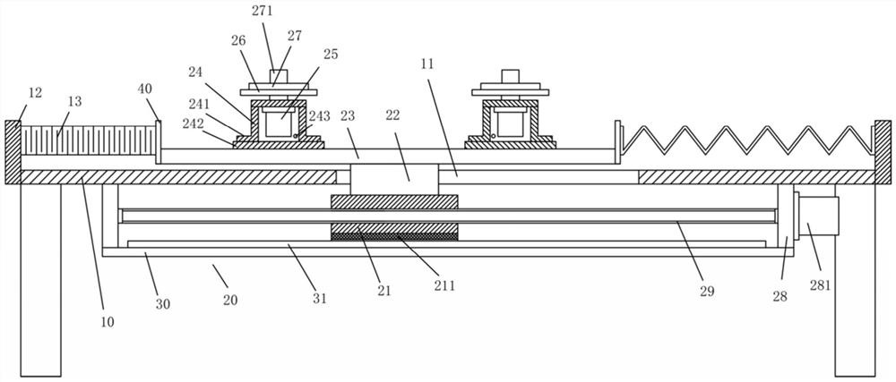
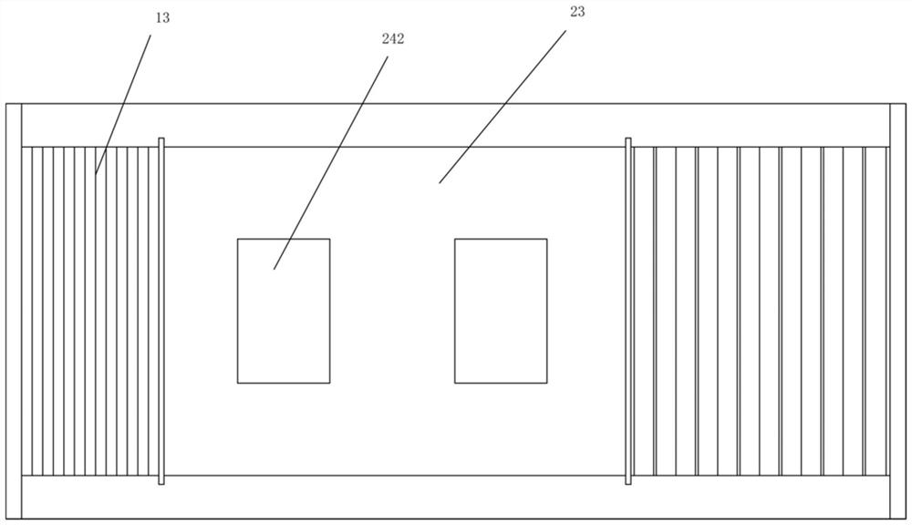
[0015] Examples, see e.g. Figure 1 to Figure 2 As shown, a moving and rotating mechanism for pump body spraying includes a frame 10, a central through groove 11 is formed in the middle of the top plate of the frame 10, and a lateral movement mechanism 20 is fixed on the bottom surface of the top plate of the frame 10 to move laterally. The top surface of the mobile block 21 of mechanism 20 is fixed with upper connecting block 22, and the top of upper connecting block 22 stretches out the top surface of the top plate of frame 10 and is fixed with transverse plate 23, and the left part of transverse plate 23 and the top of right part Both surfaces are fixed with a support base 24, the bottom surface of the top plate of the support base 24 is fixed with a rotating motor 25, the output shaft of the rotating motor 25 passes through the top surface of the top plate of the support base 24 and is fixed with a rotating fixed plate 26, and the rotating fixed plate 26 A connecting plate...


PUM


Abstract

The invention discloses a movable rotating mechanism for pump body spraying. The movable rotating mechanism comprises a rack, wherein a center through groove is formed in the middle of a top plate ofthe rack; a transverse moving mechanism is fixed to the bottom face of the top plate of the rack; an upper connecting block is fixed to the top face of a moving block of the transverse moving mechanism; the top of the upper connecting block stretches out of the top face of the top plate of the rack and is fixedly provided with a transverse plate; supporting bases are fixed to the top faces of theleft portion and the right portion of the transverse plate; rotating motors are fixed to the bottom faces of top plates of the supporting bases; and output shafts of the rotating motors penetrate thetop faces of the top plates of the supporting bases and are fixedly provided with rotating fixing plates. The movable rotating mechanism can be installed at the position of automatic spraying equipment, a pump body is fixed to a connecting plate, the pump body can be automatically moved to the position corresponding to a spraying head of the spraying equipment, and automatic spraying is achieved through the spraying head; and meanwhile, through running of the rotating motors, automatic rotation of the pump body is achieved, and therefore the outer side wall of the pump body can be automatically sprayed, automatic spraying is facilitated, the effect is good, efficiency is high, and the manual labor amount is greatly reduced.

Description

technical field [0001] The invention relates to the technical field of water pump manufacture, in particular to a moving and rotating mechanism for pump body spraying. Background technique [0002] After the existing water pump body is processed, it will be sprayed with paint. The existing methods are manual spraying. It needs to be manually placed on the hook, and then the surrounding area is manually sprayed. The efficiency is low and the effect is low. Poor, and in the spraying process, it is necessary to manually rotate the pump body, which is very troublesome. Contents of the invention [0003] The purpose of the present invention is to overcome the deficiencies of the prior art, and provide a moving and rotating mechanism for pump body spraying, which can be installed at the automatic spraying equipment, fix the pump body on the connecting plate, and can automatically move the pump body to the spraying equipment The corresponding part of the spraying head is automat...

Claims


Application Information

Patent Timeline
Patent Type & Authority Applications(China)
IPC IPC(8): B05B13/02
CPCB05B13/0228
Inventor 李乐东
Owner 李乐东
Why Eureka
Try Eureka