

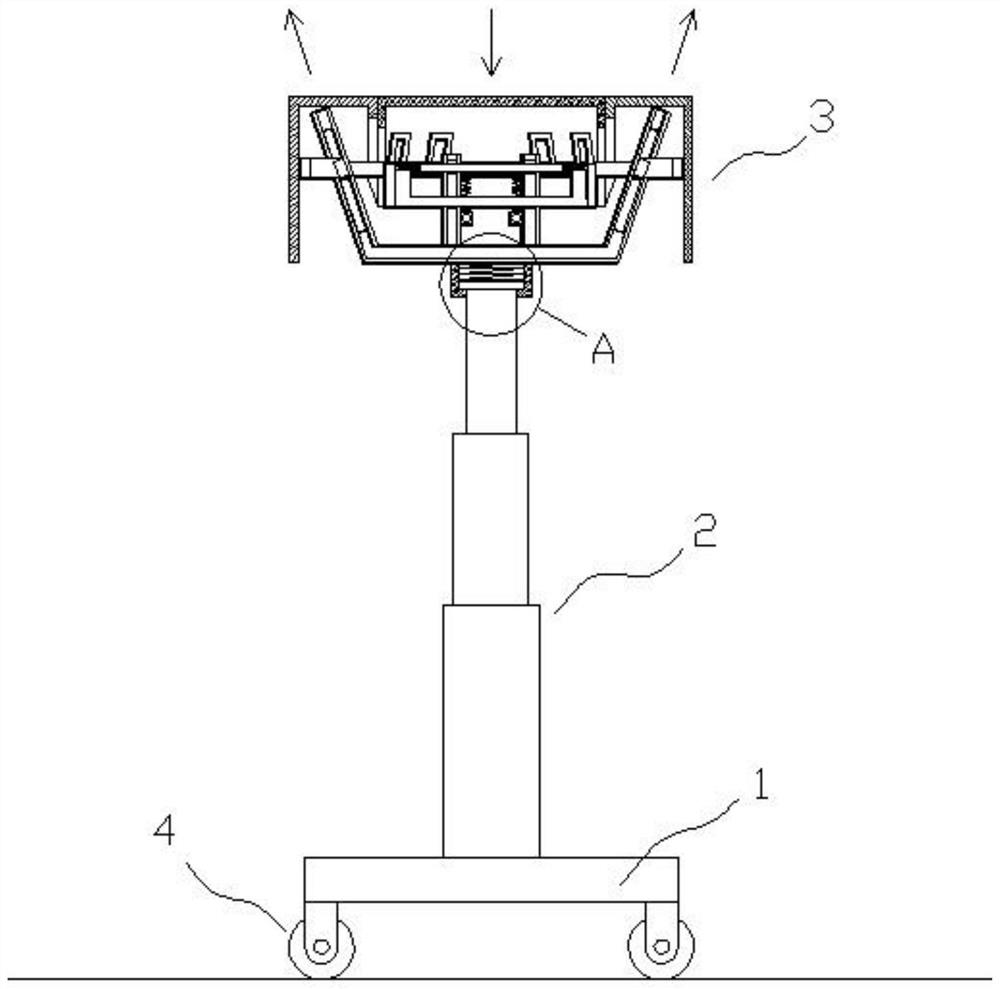
Side support structure for auxiliary installation equipment of air conditioner indoor unit
A technology for air-conditioning indoor unit and installation equipment, applied in the direction of lifting device, lifting frame, etc., can solve the problems of unstable dumping of equipment, indoor unit sliding and falling, operator and installation personnel injury, etc., to reduce the risk of side fall damage, hidden dangers, Easy to fold, store and move, improve safety and practicality
- Summary
- Abstract
- Description
- Claims
- Application Information
AI Technical Summary
Problems solved by technology
Method used
Image

Examples
Embodiment approach
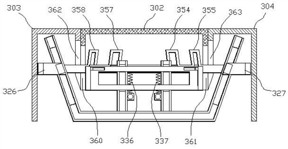
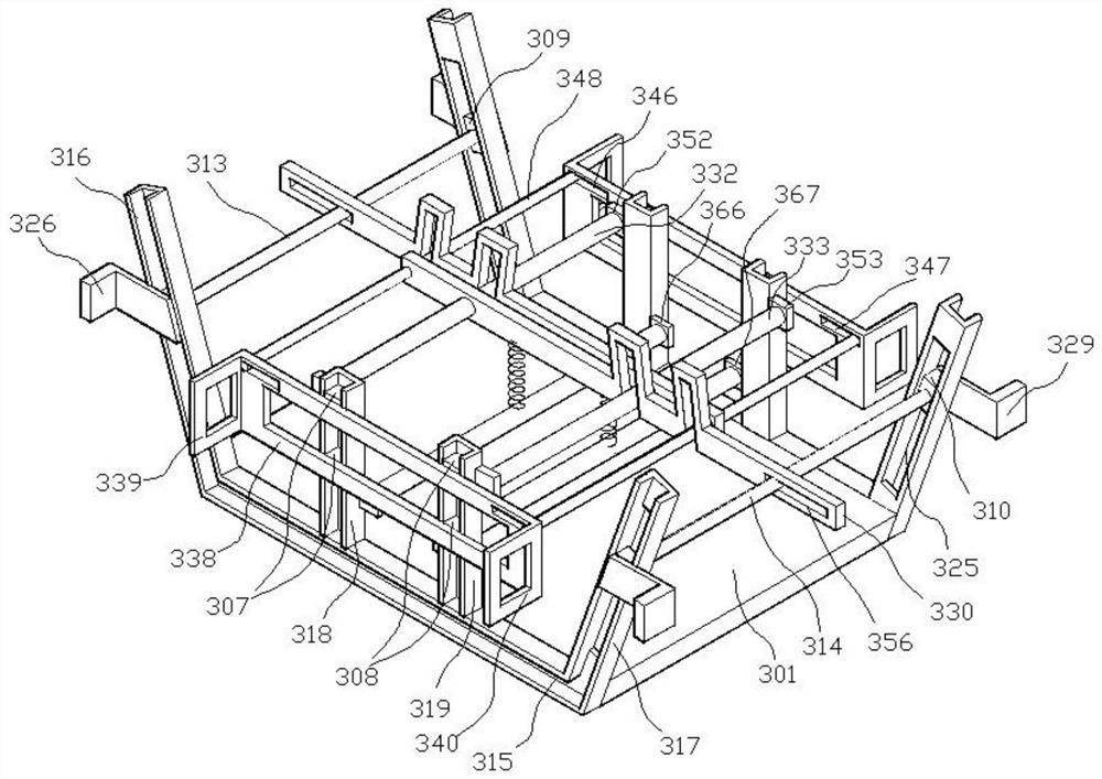
[0072] The clamping part comprises a clamping plate 930 and a plurality of clamping strips 927 arranged at the bottom of the clamping plate 930, and on the top slopes of the second foot frame 905, the third foot frame 907 and the fourth foot frame 909, there is a set of the same shape and size as the clamping plate 930. The concave cavity 928 of the second foot support 906, the third foot support 908 and the top slope of the fourth foot support 910 are all provided with a card slot 929 with the same shape and size as the clip bar 927, and the side parts on both sides of the clip plate 930 are provided with There are L-shaped sliding support bars 931, and first sliding bar grooves 932 are provided on the sides of the second foot frame 905, the third foot frame 907 and the fourth foot frame 909, and the first sliding bar grooves 932 are specifically arranged in the middle of the concave cavity 928 On both sides, the top of the above-mentioned sliding bar 931 is affixed to the sid...
PUM
 Abstract
Description
Claims
Application Information