
A wall-mounted digital TV receiving antenna

A digital TV receiving and wall-mounted technology, applied in the direction of antenna support/installation device, etc., can solve the problems of high labor cost, troublesome fixing and installation, and achieve the effect of convenient transportation, convenient installation and convenient adjustment

Active Publication Date: 2018-12-25
ZHEJIANG LONGYOU XINXIDI ELECTRONICS
View PDF10 Cites 0 Cited by
  • Summary
  • Abstract
  • Description
  • Claims
  • Application Information

AI Technical Summary

Problems solved by technology

[0002] The TV antenna is a device used by the TV to receive signals. Usually, in order to improve the quality of the received wireless signal, the receiving antenna needs to be fixed at a high place or in an open area, and a special mounting bracket is required, which is relatively troublesome to fix and install. Labor cost is high

Method used


Image

  • A wall-mounted digital TV receiving antenna
  • A wall-mounted digital TV receiving antenna
  • A wall-mounted digital TV receiving antenna

Examples


Embodiment Construction

[0036] The present invention will be further described in detail below in conjunction with the accompanying drawings and specific embodiments.

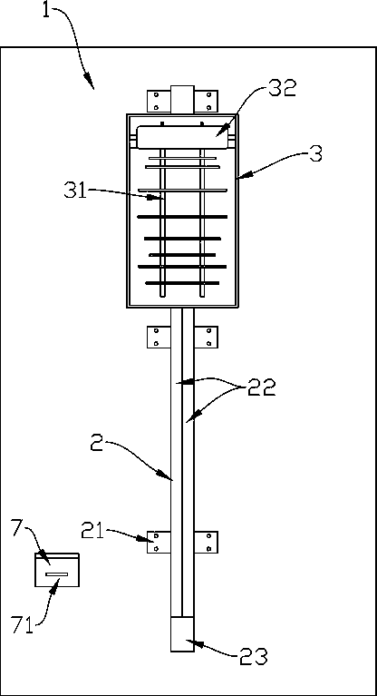
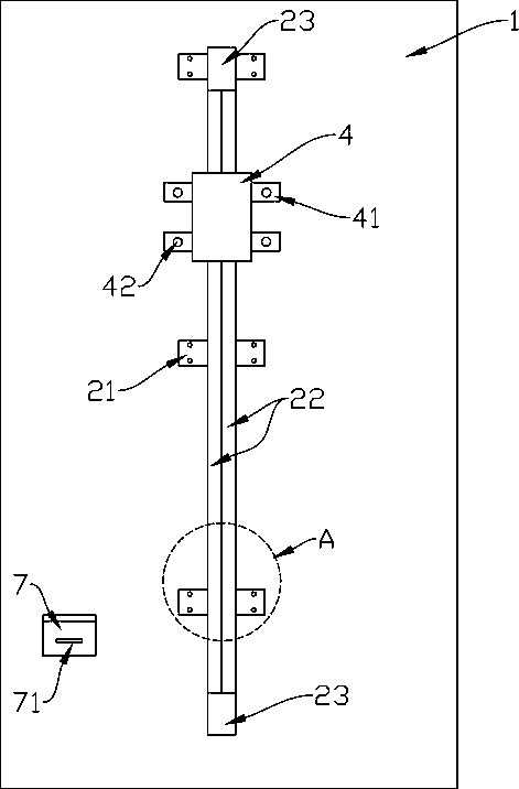
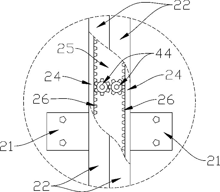
[0037] See Figure 1 to Figure 13 , a wall-mounted digital television receiving antenna, comprising a lifting column 2 arranged on the outside of a wall 1, a lifting seat 4 arranged on the lifting column 2, an antenna frame 3 arranged on the lifting seat 4, an antenna frame 3 arranged on the Antenna 31 in the middle; wherein, the lifting column 2 includes side walls 24 arranged in parallel on both sides, and an accommodating cavity 25 is formed between the two side walls 24, and a rack 26 is provided on the inner side of the side walls 24, and the side walls 24 The outer side of the wall 24 is provided with a guide groove 29; the outer surface of the lifting column 2 is covered with a flexible waterproof layer 22, the two sides of the waterproof layer 22 are fixed on the side wall 24, and the middle of the waterproof layer 22 is disco...


PUM


Abstract

The invention relates to a wall-mounted digital television receiving antenna. The wall-mounted digital television receiving antenna includes a lifting column arranged at the outer side of a wall, a lifting seat arranged on the lifting column, an antenna frame arranged on the lifting seat, and an antenna arranged in the antenna frame; the lifting column includes side walls arranged in parallel at two sides of the lifting column; the inner sides of the side walls are provided with toothed bars, and the outer sides of the side walls are provided with guide grooves; the back of the lifting seat is provided with two engaged gears; the outer sides of the gears are engaged with the toothed bars; the upper side and lower side of the back of the lifting seat are provided with guide blocks; motors are arranged in the lifting seat; the back of the antenna frame is provided with a mounting column; the upper part of the antenna frame is provided with an assembling component; the antenna is fixed on the assembling component; two ends of the assembling component are rotatably connected with the inner side wall of the antenna frame; the assembling component is provided with a pull ring; and an end portion of the telescopic shaft of a telescopic cylinder is connected with the pull ring. The height, unfolding angle and inclination angle of the antenna can be adjusted very easily, the rainwater resistance of the antenna is strong, and the service life of the antenna is long.

Description

technical field [0001] The invention belongs to the field of television signal communication, and in particular relates to a wall-mounted digital television receiving antenna. Background technique [0002] The TV antenna is a device used by the TV to receive signals. Usually, in order to improve the quality of the received wireless signal, the receiving antenna needs to be fixed at a high place or in an open area, and a special mounting bracket is required, which is relatively troublesome to fix and install. The labor cost of expending is big. [0003] In the prior art, there are some improved technologies for outdoor antennas and installation equipment, which improve the functions of the antenna and facilitate installation. For example, the Chinese utility model patent with the notification number CN202474185U discloses a base for installing an outdoor antenna, including a base, a connecting portion located on the upper surface of the base, and an extension located at the ...

Claims


Application Information

Patent Timeline
Patent Type & Authority Patents(China)
IPC IPC(8): H01Q1/12
CPCH01Q1/12
Inventor 童慧智童卿劳晓丽王涛胡柏华许红平
Owner ZHEJIANG LONGYOU XINXIDI ELECTRONICS
Learn More