Shaft product lifting device and shaft product transfer device

A technology of lifting device and transfer device, applied in the direction of lifting device, etc., can solve the problems of unsuitable post-processing equipment, not very convenient and flexible, magnetic navigation, laser navigation, two-dimensional code navigation, etc.

Active Publication Date: 2020-11-24
CHONGQING UNIV
View PDF5 Cites 0 Cited by
  • Summary
  • Abstract
  • Description
  • Claims
  • Application Information

AI Technical Summary

Problems solved by technology

The important part of the belt conveyor is the belt, and the belt is often made of composite materials. In the operating environment of spent fuel reprocessing equipment, general composite materials cannot be used at all, and the cost of developing new suitable materials is relatively high. The transportation method is not very convenient and flexible for the bar that needs to be adjusted in attitude, so the belt conveyor is not suitable for post-processing equipment
Similarly, the in-situ attitude adjustment of the bar material cannot be realized by the roller transport equipment. Although it can be transported in a curve during the transport process, considering the occupation of the site, it is not suitable as a post-processing equipment for the straight line transport mode.
The AGV car cannot be used as a post-processing device due to the navigation method and driving reasons. First, the AGV car needs its own motor as the drive, but this cannot be realized in a strong radiation environment, and the mainstream magnetic navigation, laser navigation, inertial navigation, two-dimensional Code navigation, etc. are not applicable

Method used


Image

  • Shaft product lifting device and shaft product transfer device
  • Shaft product lifting device and shaft product transfer device
  • Shaft product lifting device and shaft product transfer device

Examples


Embodiment Construction

[0048] The present invention will be further described below in conjunction with the accompanying drawings and specific embodiments, so that those skilled in the art can better understand the present invention and implement it, but the examples given are not intended to limit the present invention.

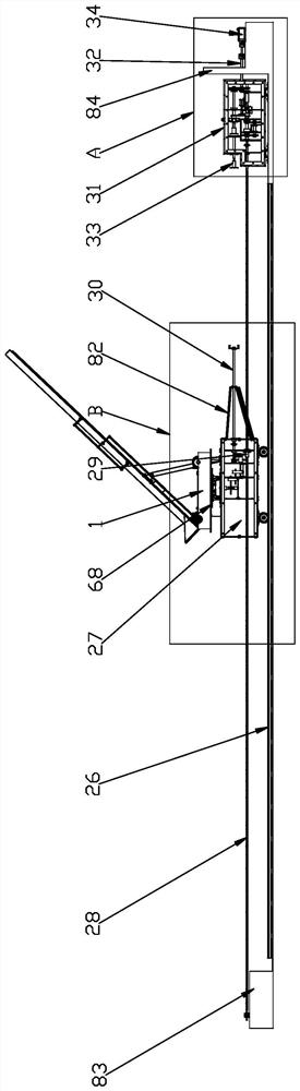
[0049] Such as figure 1 Shown is a schematic structural view of an embodiment of the shaft product transfer device of the present invention. The shaft product transfer device in this embodiment includes a linear guide rail 26 , a transfer trolley 27 installed on the linear guide rail 26 , and a transfer mechanism for driving the transfer trolley 27 to move along the linear guide rail 26 . The transfer mechanism of this embodiment includes a threaded screw 28 parallel to the linear guide rail 26 and a transmission box 31 arranged at one end of the linear guide 26 . The transfer trolley 26 is provided with a shaft product lifting device and an attitude adjustment mechanism for driv...


PUM


Abstract

The invention discloses a shaft product lifting device. A gearbox and a lifting plate are arranged. In the use process, a shaft product is placed in a placement bin, a lifting power device is started,a cover plate driving shaft and a lifting input shaft can be driven at the same time, cover plate frames cover the placement bin under the action of the cover plate driving shaft, and the technical effect of fixing the shaft product is achieved. A lifting link mechanism drives the lifting plate to rotate around a rotating shaft under the action of the lifting input shaft, so one end of the lifting plate is raised to a set height, and thus the technical effect of lifting the shaft product to a set position is achieved. The invention further provides a shaft product transfer device. Lifting andtransfer of the shaft product can be achieved, besides, the posture can be flexibly adjusted, and the shaft product transfer device can be used in working scenes such as a nuclear radiation scene.

Description

technical field [0001] The invention relates to a material conveying device, in particular to a shaft product lifting device and a transfer device thereof. Background technique [0002] Among today's main energy sources, nuclear power is the most special one, which has attracted much attention since its inception. Although my country's nuclear power technology is becoming more and more mature, the reprocessing of nuclear fuel is somewhat behind. When the nuclear fuel can no longer be used directly, the replaced spent fuel needs to be reprocessed, and the reprocessed spent fuel can be used in other ways. The reprocessing of spent fuel has become a "closed cycle" of nuclear fuel. "Inseparable part, and the research and development and manufacturing of spent fuel reprocessing equipment has become an important part of boosting the development of nuclear power. [0003] Nuclear fuel has extremely strong radiation, so the components in the reprocessing equipment that are in dire...

Claims


Application Information

Patent Timeline
Patent Type & Authority Applications(China)
IPC IPC(8): B66F9/065B66F9/075B66F9/12B66F9/20
CPCB66F9/065B66F9/07577B66F9/12B66F9/20
Inventor 杨波陈嵘华王时龙易力力任亨斌周杰曾嘉
Owner CHONGQING UNIV
Why Eureka
Try Eureka