Application method of an oil production string

A technology for producing pipe strings and application methods, which is applied in the direction of drilling pipes, casings, and production fluids. It can solve problems such as inability to work, formation crude oil cannot be lifted to the ground, and achieve the effect of reducing investment costs

Active Publication Date: 2018-11-16
PETROCHINA CO LTD
View PDF5 Cites 0 Cited by
  • Summary
  • Abstract
  • Description
  • Claims
  • Application Information

AI Technical Summary

Problems solved by technology

[0004] The purpose of the present invention is to solve the problem that the oil pump in the lifting pipe string of the high gas production well is gas-locked and unable to work, resulting in the failure of the formation crude oil to be lifted to the ground

Method used


Image

  • Application method of an oil production string
  • Application method of an oil production string

Examples


Embodiment 1

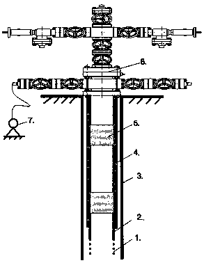
[0022] In order to solve the problem that the oil pump in the lifting string of the high gas production well is gas-locked and unable to work, resulting in the inability of the formation crude oil to be lifted to the ground, this embodiment provides an oil production string, including The self-spraying oil production wellhead 6, the casing tee of the self-spraying oil production wellhead 6 is connected with a plurality of capillary steel pipes 4, and all the capillary steel pipes 4 extend downward to the annular space between the tubing 2 and the casing 3 Inside, the outer wall of one side of the capillary steel pipe 4 is bonded to the outer wall of the oil pipe 2. The oil pipe 2 is composed of a plurality of oil pipe nipples, and a foaming device 5 is installed between adjacent oil pipe nipples. The end of the capillary steel pipe 4 is fixed on On the lowermost foaming device 5 , the lower end of the oil pipe 2 is connected with a floral tube 1 , and the floral tube 1 is close...

Embodiment 2

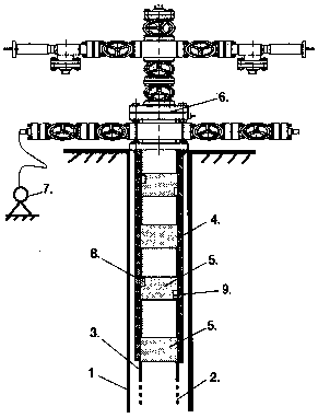
[0029] On the basis of Example 1, the foaming device 5 is provided with an upper liquid inlet hole 8 and a lower liquid inlet hole 9 , and both the upper liquid inlet hole 8 and the lower liquid inlet hole 9 are close to the inner wall of the oil pipe 2 .

[0030] On deep wells, due to the high lifting height, multiple foaming devices need to be installed, and the foaming agent needs to be replenished during the lifting process. This embodiment provides the following figure 2 In the oil production string shown, the plunger pump 7 continuously injects foaming agent into the capillary steel pipe 4, and the foaming agent gradually flows downward along the capillary steel pipe 4, and a part of the foaming agent follows the upper liquid inlet hole 8 and the lower liquid inlet. The hole 9 flows to the foaming device 5; a part of the foaming agent flows directly along the capillary steel pipe 4 into the annular space between the oil pipe 2 and the casing 3, and forms a mixed liquid w...

Embodiment 3

[0034] On the basis of Embodiment 2, the foaming device 5 is composed of a housing, a helical stirrer and a storage lithium battery in the housing, and the helical stirrer is electrically connected to the storage lithium battery.

[0035] The steel grade and outer diameter of the foaming device 5 are the same as those of the oil pipe 2, the length is 10 meters, and the connection with the oil pipe 2 is realized by a screw. There is a spiral stirrer inside the foaming device 5, and the driving force of the stirrer is provided by a storage lithium battery. When the fluid containing the foaming agent flows through the foaming device 5, the stirrer will automatically start when it senses the flow of the liquid, making the liquid The foaming agent quickly turns into a large amount of foam, and the foam carries the crude oil in the wellbore, and boosts the fluid in the wellbore through the tubing to go up to the head of the self-spraying production well.

[0036] The specific number...


PUM


Abstract

The invention provided oil extraction production string of a high vapor liquid ratio oil extraction well, through providing a foam rising device on an oil pipe, enables the foam rising agent to produce a large amount of foams to carry the crude oil of a well bottom, under the lifting action of the earth formation gas inside a pit shaft, lifts the crude oil upwards along the pit shaft to the ground. The pipe pillar fully utilizes the natural energy of inner earth formation gas, achieves the lifting of the crude oil of the well bottom, and avoids the problems of low pump efficiency and no fluid coming caused by the inner earth formation gas affecting the oil drawing pump in the oil extraction process of the rod pumping of normal oil pumping machine. Meanwhile the oil extraction pipe pillar can remove the oil pumping machine and the oil drawing pump and other installations, which lowers the investment costs, and provides a new means for the lifting of the oil extraction well.

Description

technical field [0001] The invention belongs to the technical field of oilfield oil and gas recovery engineering, and in particular relates to an application method of an oil recovery production string suitable for high gas content oil recovery wells. Background technique [0002] The oil recovery methods using gas as the main oil displacement medium are collectively referred to as gas flooding. According to the displacement medium, gas flooding mainly includes N 2 flooding, CO 2 There are several types of flooding, air flooding, flue gas flooding, and light hydrocarbon gas flooding. Theoretical studies and domestic and foreign oil field practices have shown that gas flooding is an effective way to enhance oil recovery. At present, gas flooding has become a very important technical means in the enhanced oil recovery method. [0003] After gas flooding in the oil field, the viscosity of the crude oil in the formation decreases and the fluidity becomes stronger, but it als...

Claims


Application Information

Patent Timeline
Patent Type & Authority Patents(China)
IPC IPC(8): E21B17/00E21B43/22
CPCE21B17/00E21B43/16
Inventor 石海霞甘庆明周志平黄伟赵春梁毅樊松姚洋雷宇郭靖苏祖波刘明
Owner PETROCHINA CO LTD
Why Eureka
Try Eureka