
Aircraft deceleration method and device based on air rudder

An air rudder and aircraft technology, applied in the aerospace field, can solve problems such as insufficient maturity, and achieve the effects of simple deceleration method, stable deceleration and attitude, and rapid deceleration effect

Active Publication Date: 2022-01-18
THE GENERAL DESIGNING INST OF HUBEI SPACE TECH ACAD
View PDF5 Cites 0 Cited by
  • Summary
  • Abstract
  • Description
  • Claims
  • Application Information

AI Technical Summary

Problems solved by technology

[0003] With the rapid development of aircraft technology, at this stage, new deceleration technologies such as flexible aerodynamic reducers, reverse thrust reducers, and combined deceleration devices have been developed. However, due to the lack of maturity of the above technologies, these new deceleration technologies still exist in the field of aircraft. certain limitations

Method used


Image

  • Aircraft deceleration method and device based on air rudder
  • Aircraft deceleration method and device based on air rudder
  • Aircraft deceleration method and device based on air rudder

Examples


Embodiment 1

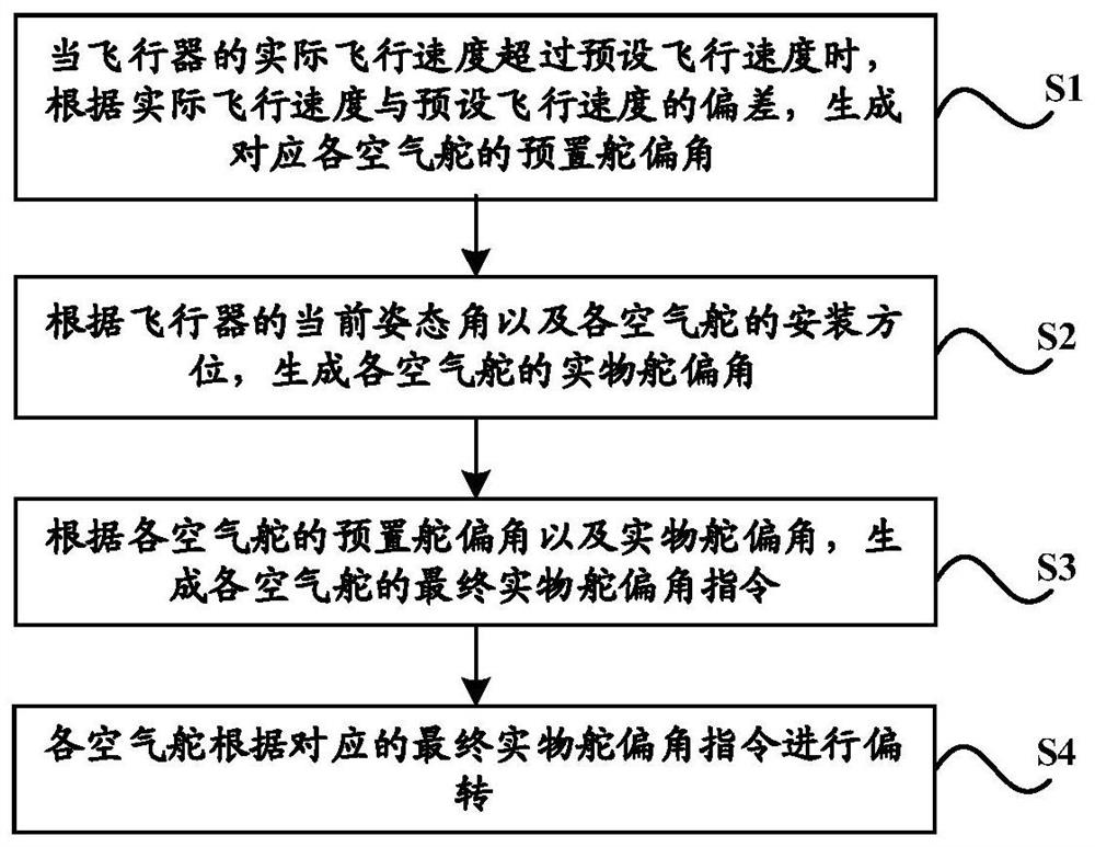
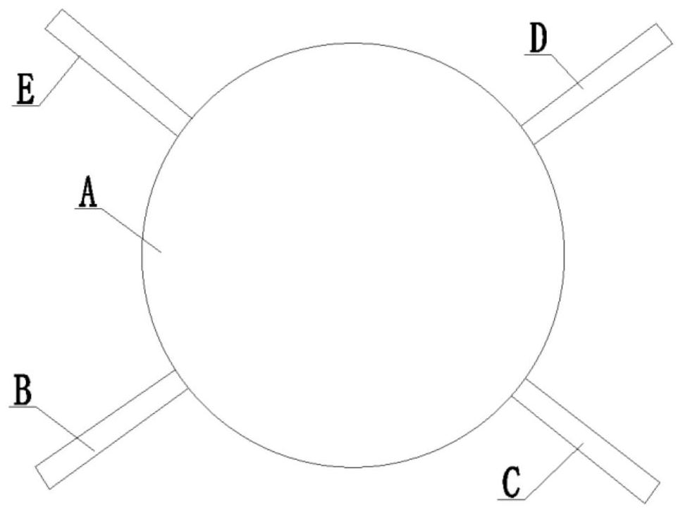
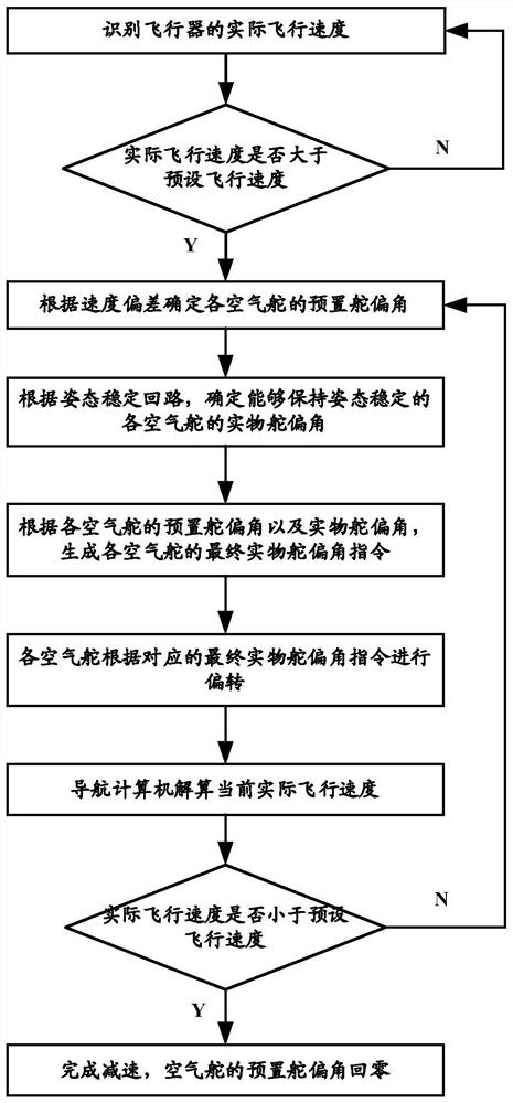
[0065] see Figure 1~3 As shown, the embodiment of the present invention provides a method for decelerating an aircraft based on an air rudder, in which a plurality of air rudders are symmetrically arranged at the tail of the aircraft, and the method includes the following steps:

[0066] S1. When the actual flight speed of the aircraft exceeds the preset flight speed, according to the deviation between the actual flight speed and the preset flight speed, a preset rudder deflection angle corresponding to each air rudder is generated;

[0067] S2, according to the current attitude angle of the aircraft and the installation orientation of each air rudder, generate the physical rudder deflection angle of each air rudder;

[0068] S3. According to the preset rudder deflection angle of each air rudder and the physical rudder deflection angle, generate the final physical rudder deflection angle command of each air rudder;

[0069] S4. Each air rudder is deflected according to the c...

Embodiment 2

[0114] see Figure 4 As shown, the embodiment of the present invention provides a deceleration device for an aircraft based on an air rudder. The tail of the aircraft is symmetrically provided with a plurality of air rudders. The device includes:

[0115] Flight speed monitoring module 1, which is used to identify the actual flight speed of the aircraft;

[0116] Attitude angle monitoring module 2, which is used to identify the current attitude angle of the aircraft;

[0117] The first calculation module 3 is used to generate the preset rudder deflection angle corresponding to each air rudder according to the deviation between the actual flight speed and the preset flight speed when the actual flight speed of the aircraft exceeds the preset flight speed;

[0118] Second calculation module 4, it is used for according to the current attitude angle of aircraft and the installation orientation of each air rudder, generates the physical rudder deflection angle of each air rudder; ...


PUM


Abstract

The application relates to a deceleration method and device for an aircraft based on an air rudder, and relates to the field of aerospace technology. A plurality of air rudders are arranged symmetrically at the tail of the aircraft. The method includes the following steps: when the actual flight speed of the aircraft exceeds the preset flight speed , according to the deviation between the actual flight speed and the preset flight speed, the preset rudder deflection angle corresponding to each air rudder is generated; according to the current attitude angle of the aircraft and the installation orientation of each air rudder, the physical rudder deflection angle of each air rudder is generated; According to the preset rudder deflection angle of each air rudder and the actual rudder deflection angle, the final physical rudder deflection angle command of each air rudder is generated; each air rudder deflects according to the corresponding final physical rudder deflection angle command. This application does not need to add an additional deceleration device, and the aircraft's own air rudder can be used to control its flight speed, and at the same time, it can also ensure the stability of the flight attitude of the aircraft during deceleration.

Description

technical field [0001] The invention relates to the field of aerospace technology, in particular to an air rudder-based aircraft deceleration method and device. Background technique [0002] Traditional aircraft deceleration methods mainly include rigid aerodynamic decelerators, parachute deceleration, etc., while traditional aircraft deceleration methods require additional deceleration and anti-rotation devices on the aircraft, which will increase the negative mass of the aircraft and bring new problems to the aircraft structure design and control system. to greater difficulty. [0003] With the rapid development of aircraft technology, at this stage, new deceleration technologies such as flexible aerodynamic reducers, reverse thrust reducers, and combined deceleration devices have been developed. However, due to the lack of maturity of the above technologies, these new deceleration technologies still exist in the field of aircraft. Certain limitations. [0004] Therefore...

Claims


Application Information

Patent Timeline
Patent Type & Authority Patents(China)
IPC IPC(8): B64C9/32
CPCB64C9/32
Inventor 赵海龙鲁艳清龙垚松孙利华余先伟王源杰马新普万方
Owner THE GENERAL DESIGNING INST OF HUBEI SPACE TECH ACAD
Learn More