A pressure relief valve applied to an air compressor

A pressure relief valve and air compressor technology, which is applied in the field of pressure relief valves, can solve problems such as personal injury, and achieve the effect of improving safety and realizing release

Active Publication Date: 2022-04-29
大庆烯城炟石油技术开发有限公司
View PDF13 Cites 0 Cited by
  • Summary
  • Abstract
  • Description
  • Claims
  • Application Information

AI Technical Summary

Problems solved by technology

[0002] At present, the structure of the relief valve is an unloading spool and a damping spool connected by bolts, nuts, and guide posts to form a dumbbell-shaped integral spool, and rubber sealing materials are installed on the damping spool. The relief valve is also called a pressure relief valve. The compression pressure in the air storage tank of the compressor is greater than the rated pressure value, and the pressure relief valve can be opened to release the pressure and protect the air storage tank; the current pressure relief valve generally has a pressure relief hole on the side wall of the valve body, and uses the pressure relief valve to release the pressure. The pressure relief hole, when the pressure in the air storage tank is too high, the compressed air released by the pressure relief valve will be ejected from the pressure relief hole, which may cause personal injury

Method used


Image

  • A pressure relief valve applied to an air compressor
  • A pressure relief valve applied to an air compressor
  • A pressure relief valve applied to an air compressor

Examples


Embodiment

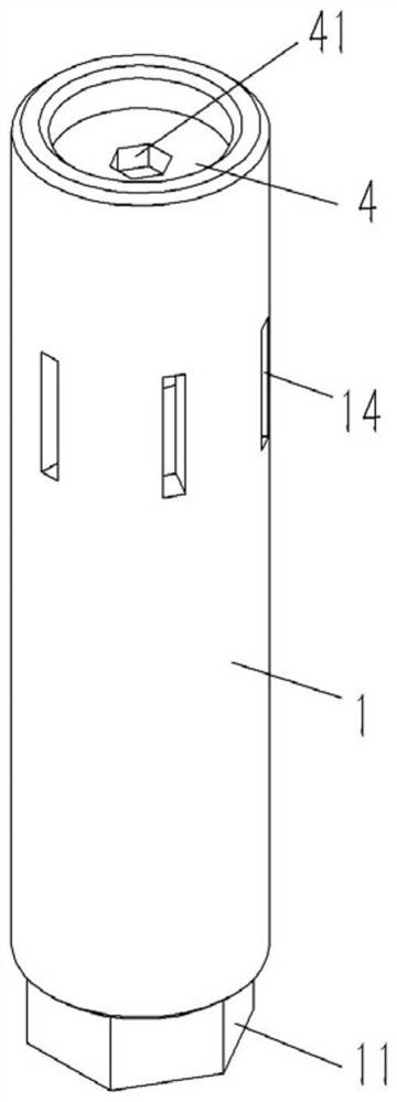
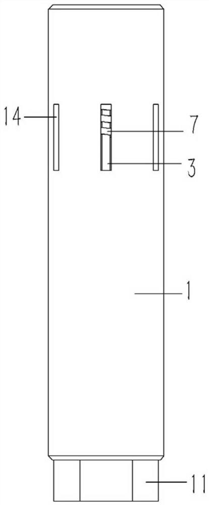
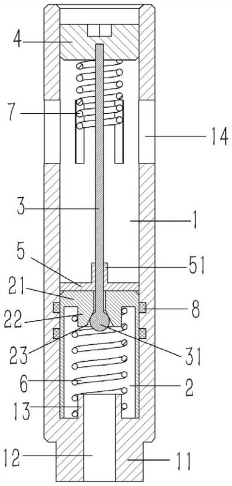
[0017] Example: see Figures 1 to 3 As shown, a pressure relief valve applied to an air compressor includes a vertical tubular valve body 1, the lower end of the valve body 1 is formed with a regular hexagonal connecting block 11, and the connecting block 11 is formed with a valve body 1 The inner hole is connected with the threaded connecting hole 12, and the upper end surface of the connecting block 11 is formed with a lower connecting sleeve 13 connected with the threaded connecting hole 12; the lower end of the inner hole of the valve body 1 is inserted with a cylindrical ring-shaped valve core 2 and extension spring 6, the upper end of the spool 2 is formed with an annular end cover 21, and the lower end surface of the end cover 21 is formed with an upper connecting sleeve 22 communicating with the center hole of the end cover 21, and the upper connecting sleeve 22 is formed There is a conical valve hole 23; the upper end sleeve of the extension spring 6 is fixed on the u...


PUM


Abstract

The invention discloses a pressure relief valve applied to an air compressor, which comprises a valve body, a cylindrical ring-shaped valve core and a tension spring are inserted at the lower end of the valve body hole, and a ring-shaped end is formed on the upper end of the valve core. Cover, the lower end surface of the end cover is formed with an upper connecting sleeve connected with the center hole of the end cover, and a conical valve hole is formed in the upper connecting sleeve; the upper end sleeve of the extension spring is fixed on the upper connecting sleeve, and the upper connecting sleeve of the extension spring The lower end sleeve is fixed on the lower connecting sleeve; the lower end of the valve stem is formed with a spherical valve head, the valve head is pressed against the inner wall of the valve hole on the valve core, the upper end of the valve stem is plugged and fixed on the positioning block, and the positioning block is plugged It is fixed in the valve body; a safety block is inserted on the valve stem, and the safety block covers the center hole on the end cover of the valve core and leans against the end cover; there are several vertical roads formed on the valve body on the upper side of the safety block. exhaust slot.

Description

technical field [0001] The invention relates to the technical field of air compressors, in particular to a pressure relief valve applied to air compressors. Background technique [0002] At present, the structure of the relief valve is an unloading spool and a damping spool connected by bolts, nuts, and guide posts to form a dumbbell-shaped integral spool, and rubber sealing materials are installed on the damping spool. The relief valve is also called a pressure relief valve. The compression pressure in the air storage tank of the compressor is greater than the rated pressure value, and the pressure relief valve can be opened to release the pressure and protect the air storage tank; the current pressure relief valve generally has a pressure relief hole on the side wall of the valve body, and uses the pressure relief valve to release the pressure. The pressure relief hole, when the pressure in the air storage tank is too high, the compressed air released by the pressure relie...

Claims


Application Information

Patent Timeline
Patent Type & Authority Patents(China)
IPC IPC(8): F16K17/04F16K17/164F16K47/08
CPCF16K17/04F16K17/164F16K47/08
Inventor 胡中和
Owner 大庆烯城炟石油技术开发有限公司
Why Eureka
Try Eureka