
Pipe assembly, performance measuring method thereof and control rod water pressure driving system

A technology of tube assembly and hydraulic cylinder, which is used in liquid/vacuum measurement for liquid tightness measurement, measurement device, and mechanical component testing, etc. It can solve the problems of motion displacement compensation of secondary and large deformation, large dispersion of metal hoses, etc., to achieve the effects of reducing operating costs, credible high number of movements, and small dispersion of failure times.

Active Publication Date: 2020-12-01
TSINGHUA UNIV
View PDF12 Cites 1 Cited by
  • Summary
  • Abstract
  • Description
  • Claims
  • Application Information

AI Technical Summary

Problems solved by technology

[0004] However, metal expansion joints are generally suitable for motion displacement compensation of large size, low frequency, and small deformation, and cannot meet the motion displacement compensation of small size, high frequency, and large deformation of hydraulic drive mechanisms.
Although the metal hose can satisfy the motion displacement compensation of the hydraulic drive mechanism with small size, high frequency, and large deformation, the number of failures of the metal hose has a large dispersion, and its credible number of motions is 50,000 times, which is difficult to meet. The hydraulic drive mechanism needs more than 300,000 times, or even millions of times of movement

Method used


Image

  • Pipe assembly, performance measuring method thereof and control rod water pressure driving system
  • Pipe assembly, performance measuring method thereof and control rod water pressure driving system
  • Pipe assembly, performance measuring method thereof and control rod water pressure driving system

Examples


Embodiment Construction

[0060] In order to make the purpose, technical solutions and advantages of the invention clearer, the technical solutions in the invention will be clearly described below in conjunction with the accompanying drawings in the invention. Obviously, the described embodiments are part of the embodiments of the invention, not all of them. Example. Based on the embodiments of the invention, all other embodiments obtained by persons of ordinary skill in the art without making creative efforts belong to the protection scope of the invention.

[0061] In the description of the embodiments of the present invention, it should be noted that the terms "center", "longitudinal", "transverse", "upper", "lower", "front", "rear", "left", "right" , "vertical", "horizontal", "top", "bottom", "inner", "outer" and other indicated orientations or positional relationships are based on the orientations or positional relationships shown in the drawings, and are only for the convenience of describing thi...


PUM


Abstract

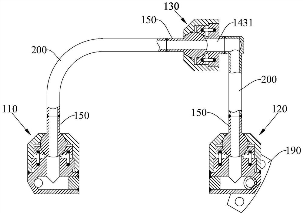
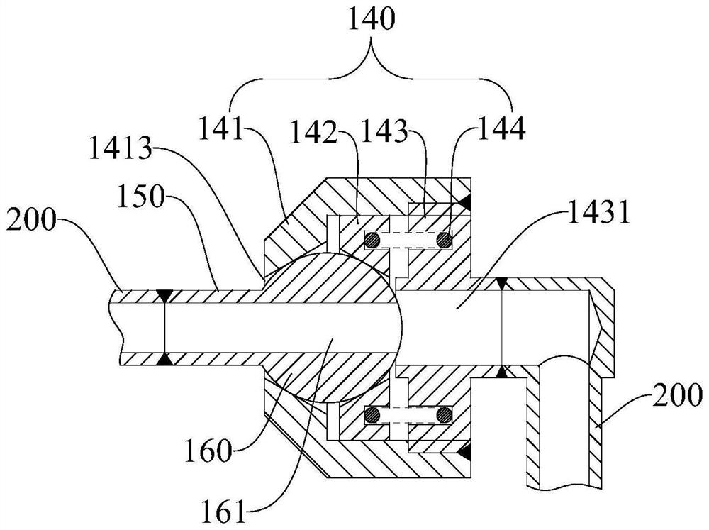
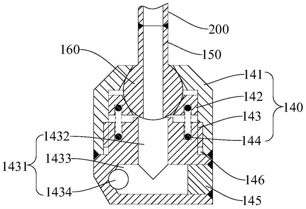
The invention relates to the field of fluid conveying pipelines, and provides a pipe assembly, a performance measuring method thereof and a control rod water pressure driving system. The pipe assemblycomprises a first end joint, a middle joint and a second end joint. Each of the first end joint, the middle joint and the second end joint comprises a joint body, an extension pipe and a joint ball,the joint ball is formed at the end of the extension pipe, and a first through hole communicated with the extension pipe is axially formed in the joint ball in a penetrating manner; a joint cavity isformed in the joint body; a mounting through hole and a matching through hole which are communicated with the joint cavity are formed in two sides of the joint body; the joint ball is rotatably arranged in the joint cavity; the extension pipe extends out of the mounting through hole; and the first through hole is communicated with the matching through hole; the extension pipe of the middle joint and the matching through hole are respectively communicated with the extension pipes of the first end joint and the second end joint through first connecting pipes. The pipe assembly, the performance measuring method thereof and the control rod water pressure driving system have the advantages of small dispersion degree of failure times and high credible movement times, and can be suitable for small-size, high-frequency and large-deformation movement displacement compensation.

Description

technical field [0001] The invention relates to the field of fluid delivery pipelines, in particular to a pipe assembly, a performance measurement method thereof, and a control rod hydraulic drive system. Background technique [0002] When transporting fluid, in order to absorb the dimensional changes of pipelines, conduits, containers, etc. caused by thermal expansion and contraction, or to compensate for the axial, lateral and angular displacement of pipelines, conduits, containers, etc., metal expansion joints are usually used or metal hose. [0003] Taking the control rod hydraulic drive system as an example, the hydraulic drive mechanism is placed in the high temperature, high pressure and irradiation environment in the reactor pressure vessel. Cooperate to realize the step-up, step-down and rod-down functions of the control rod. Wherein, the outer casing of the transmission hydraulic cylinder is fixedly connected with the inner casing of the lifting hydraulic cylinde...

Claims


Application Information

Patent Timeline
IPC IPC(8): G01M3/04G01M3/02G01M13/00
CPCG01M3/02G01M3/04G01M13/00
Inventor 薄涵亮王金海刘潜峰赵陈儒秦本科
Owner TSINGHUA UNIV
Learn More